Cutting, tapping and machining
Precision Cutting and Tapping of Aluminium Profiles: The Tolerance That Actually Matters
Most drawings ask for ±0.1 mm because it sounds precise. On a frame, the number that decides whether the kit assembles is usually not the cut length at all — it is the squareness of the end face, and it multiplies by fifty on a two metre member. Here is the tolerance chain, the tap drill and engagement numbers, and the specification sheet that prevents a remake.
Quick answer
- Cut length and cut squareness are two different tolerances, and on long members squareness matters far more. A cut face that is out of square by 0.1 mm across a 40 mm section tilts the member by that angle, and over a 2,000 mm length the far end lands 5 mm away from where it should be.
- Use the multiplier: far-end error = face deviation × (member length ÷ section width). For a 40 mm section it is 50 times the deviation; for a 2,000 mm member it is enormous compared with the length tolerance you were worrying about.
- Length tolerance only has to be tight where the error cannot escape. In a slotted frame the T-nut slides, so ±0.5 mm on a member length is normally invisible at assembly. It is not invisible on a member that has to fit between two fixed faces, or in a stack where the errors add.
- Tap drill for a 75 per cent thread: M3 2.5 mm, M4 3.3, M5 4.2, M6 5.0, M8 6.8, M10 8.5, M12 10.2. For 6063 use about 0.1 mm larger to reduce tapping torque and tap breakage, giving roughly 65 per cent thread.
- Thread engagement in aluminium should be 1.5 diameters minimum and 2 diameters preferred. Worked through, 1.5D develops about two thirds of a class 8.8 bolt’s strength in 6063-T5, and 2D develops about nine tenths. Never assume a tapped hole in aluminium develops the full bolt load.
- Tapping speed for 6063 with an M2 HSS tap is 20 to 40 m/min, which is 1,061 to 2,122 rpm for M6 and 796 to 1,592 rpm for M8. Reduce by 25 per cent for a blind hole, which is what every profile end-tap is. Feed is pitch × rpm, so M8 at 1.25 mm pitch and 800 rpm feeds at 1,000 mm/min.
Also searched as: aluminium profile cutting service, cut to length aluminium extrusion tolerance, tapping aluminium profiles, aluminium profile machining service, pre-machined profile kits, aluminium extrusion end tapping, cut and tapped aluminium frame kit.
Two tolerances, and only one of them ruins assemblies
When a drawing says “cut to ±0.1 mm”, it is describing one number. The delivered part has at least four, and they fail in different ways.
| What it is | What it controls | Typical achievable | What it costs to tighten |
|---|---|---|---|
| Cut length | How long the member is along its axis | ±0.5 mm on a stop-controlled saw | Little, until you go below ±0.2 mm |
| Cut squareness | Whether the end face is perpendicular to the axis | 0.1 mm face deviation on a good saw cut | A lot: needs a milled end face |
| Mitre angle | The 45° or other angled cut | ±0.25° | Little on a mitre-capable saw |
| Burr at the cut | Whether hardware can slide into the slot | Removed by hand or brush | Labour only, but easy to skip |
Cut length is the one buyers fixate on, and it is the one the joint usually forgives. Squareness is the one that gets overlooked, and it does not get forgiven at all.
Why squareness multiplies
A cut that is not perpendicular to the axis leaves the end face at an angle. When that face is butted against a square mating face, the whole member is rotated by that angle. The rotation is tiny at the joint and enormous at the far end, because the error grows with distance.
Far-end error = face deviation × (member length ÷ section width)
A 40 mm square section over 2,000 mm gives a multiplier of 50. A 0.1 mm deviation across the cut face becomes 5 mm at the far end. A 0.2 mm deviation becomes 10 mm. This is why a frame can have every member within its length tolerance and still not close at the last corner.
Put real numbers on it. If you are assembling a 2,000 mm portal frame and both uprights are cut 0.1 mm out of square in the same direction, the top beam is displaced 5 mm sideways. If they are out of square in opposite directions, the span between them is unchanged but both are leaning, and the diagonals differ by 10 mm. Either way, no length tolerance on the drawing predicted it.
The practical rule. For members shorter than about 300 mm, squareness is a minor term and cut length dominates. For members longer than about 1,000 mm, squareness dominates and the length tolerance is almost irrelevant. If you can only specify one tight tolerance on a long member, specify the squareness of the end face, not the length.
And when length really does matter
There are three cases where the cut length is the critical tolerance and the joint will not absorb it.
- A member that fits between two fixed faces. A spacer, a panel retainer, or a cross member between two uprights that are already bolted down. The error cannot escape, so it becomes a fit problem.
- A stack in the same direction. Five members of ±0.5 mm in one direction is ±2.5 mm worst case. If the design has 1 mm of clearance, it fails. Either tighten the tolerance or — better — cut the stack members to a common reference so the errors do not add.
- A matched pair. Two parallel rails carrying a gantry. If one is 0.5 mm longer than the other, the gantry skews, and no amount of bolt tightening fixes it.
Specify the tolerance asymmetrically. A member that is 0.5 mm too long can be cut again. A member that is 0.5 mm too short is scrap. So write +0 / −0.5 mm instead of ±0.25 mm. You get the same assembly result, the shop cuts to the low side of the band, and you eliminate the most expensive failure mode in the whole operation: the member that cannot be recovered.
Tapping: the numbers that decide whether the joint holds
An end tap in a profile is a blind hole in a soft alloy, in a bore of fixed and limited diameter. That combination constrains the thread size, the drill size, the depth and the speed. Get any of the four wrong and the joint either strips or the tap breaks.
Tap drill sizes
| Thread | Pitch | Tap drill, 75 % thread | For 6063, ~65 % thread | Form tap hole |
|---|---|---|---|---|
| M3 | 0.50 mm | 2.50 mm | 2.60 mm | 2.75 mm |
| M4 | 0.70 mm | 3.30 mm | 3.40 mm | 3.65 mm |
| M5 | 0.80 mm | 4.20 mm | 4.30 mm | 4.80 mm |
| M6 | 1.00 mm | 5.00 mm | 5.10 mm | 5.50 mm |
| M8 | 1.25 mm | 6.80 mm | 6.90 mm | 7.40 mm |
| M10 | 1.50 mm | 8.50 mm | 8.60 mm | 9.30 mm |
| M12 | 1.75 mm | 10.20 mm | 10.40 mm | 11.10 mm |
Two things about this table change real orders. First, the “for 6063” column is deliberately about 0.1 mm larger than the nominal tap drill. Aluminium is gummy, and a 75 per cent thread in a soft alloy increases tapping torque and the risk of a broken tap deep in a bore. Dropping to roughly 65 per cent thread costs a small amount of strength and removes most of that risk.
Second, the form tap column is much larger. A forming tap does not cut material, it displaces it, so the starting hole has to contain the volume of the thread it is about to create. That is why an M8 forming tap needs a 7.4 mm hole where an M8 cutting tap needs 6.8 mm. If your centre bore is sized exactly to the cutting tap drill, you cannot form-tap it without opening the bore first. For a blind hole in 6063, form tapping is often the better process because there is no chip to evacuate, and chip evacuation is the main cause of tap failure in blind holes.
Thread engagement, worked through
The rule of thumb is that aluminium needs 1.5 diameters of engagement as a minimum and 2 diameters as a preference, against roughly 0.8 diameters for steel. The reason is shear strength: the internal thread in a soft alloy shears before a high-grade bolt breaks. It is worth seeing how much that matters in numbers.
| Thread in 6063-T5 | Engagement 1.5D | Stripping load | Engagement 2D | Stripping load | Class 8.8 bolt breaks at |
|---|---|---|---|---|---|
| M6 × 1.0 | 9 mm | 10.9 kN | 12 mm | 14.5 kN | 16.1 kN |
| M8 × 1.25 | 12 mm | 19.5 kN | 16 mm | 26.0 kN | 29.3 kN |
| M10 × 1.5 | 15 mm | 29.3 kN | 20 mm | 39.0 kN | 46.4 kN |
| M12 × 1.75 | 18 mm | 40.2 kN | 24 mm | 53.6 kN | 67.4 kN |
The pattern is consistent: 1.5D gives roughly two thirds of the bolt’s strength, 2D gives roughly nine tenths. To match a class 8.8 bolt in 6063-T5 you need about 2.25D. These figures assume the parent metal is at the lower certified band, 160 MPa tensile, and that the load is static. For a dynamic or vibrating joint, apply a safety factor on top.
The design consequence. A tapped hole in an aluminium profile is not a way to develop full bolt strength. It is a way to hold a joint that is loaded in shear or lightly in tension. Where a joint carries real tension — a lifting point, a cantilever root, anything overhead — use a through-bolt with a steel nut rather than a tapped hole, or size the thread two sizes up. This is the reason the centre bore of a 40 series profile exists at all: it lets a long bolt pass right through the member and be fastened at the far end with a nut that can be steel.
Tapping speed
6063 with an M2 HSS tap runs at 20 to 40 m/min surface speed. Converted to spindle speed for a blind hole, which is what a profile end tap always is, and with the 25 per cent reduction that blind holes require:
| Thread | Through hole, M2 HSS | Blind hole, reduced 25 % | Feed at mid-range |
|---|---|---|---|
| M6 × 1.0 | 1,061 – 2,122 rpm | 796 – 1,592 rpm | 1,200 mm/min |
| M8 × 1.25 | 796 – 1,592 rpm | 597 – 1,194 rpm | 1,120 mm/min |
| M10 × 1.5 | 637 – 1,273 rpm | 478 – 955 rpm | 1,075 mm/min |
| M12 × 1.75 | 530 – 1,061 rpm | 398 – 796 rpm | 1,045 mm/min |
Feed is pitch multiplied by rpm, which is why it barely changes with thread size: a bigger tap turns more slowly and takes a bigger bite per turn. On a machine without rigid tapping, start at 70 per cent of these values and work up. Use cutting oil rather than an emulsion for tapping aluminium; the adjustment for emulsion is another 15 per cent off the speed.
The anodising trap
This one catches people after the machining is already correct, which makes it expensive.
Anodising grows an oxide layer on the surface of the aluminium. It is not a coating sitting on top of the metal; it consumes some of the metal and builds outward, so a finished surface ends up slightly proud of the original. A typical protective anodic layer of 15 µm moves the surface by roughly 7 µm outward, because about half the layer grows into the metal and about half grows out of it.
Two consequences follow, and they pull in opposite directions depending on what you are making.
- Bores get smaller. A 15 µm layer takes roughly 15 µm off the diameter of a hole, because both sides grow inward. That is invisible on an M8 thread with a 1.25 mm pitch, but it is significant on a precision bore or a press-fit pin.
- Outside dimensions get bigger. The same layer adds about 15 µm to an overall width. Again irrelevant for a frame member, relevant for a part that has to slide into a groove.
Cut and tap first, anodise second. If you cut anodised stock, the cut face is bare aluminium. On a clear anodised finish that is almost invisible. On a black or dyed finish it is a bright silver ring at every cut end, and it has no protective layer at all, so it is the first place corrosion starts. The order of operations therefore has to be: machine, then finish. Which means the cut list must be final before the finishing step is booked, and there are no site adjustments afterwards. If a frame is likely to need adjustment on site, leave it in mill finish, or accept the visible cut faces.
The specification sheet to send with the order
Most machining errors are not machining errors. They are specification gaps that the shop filled in with an assumption. A one-page cut list removes almost all of them.
Inspecting a cut and tapped kit on arrival
Six checks, ordered so that the ones most likely to catch a real problem come first.
| Check | How | What it catches |
|---|---|---|
| Measure the longest members first | Tape or a bench rule against the drawing | A length error that will not close at assembly |
| Check squareness on a long member | Stand it on a surface plate or against a square and feel the gap at the end face | The error that multiplies by fifty and ruins the frame |
| Run a thread gauge through every tapped hole | Go / no-go gauge, or thread a known bolt to full depth by hand | A tap that ran short, or a thread cut with the wrong drill |
| Slide a T-nut along every slot | By hand, full length of the member | A burr at the cut that will stop assembly halfway |
| Check the tapped depth | Depth gauge, or mark a bolt and count the turns | A hole that is nominally tapped but too shallow for the intended bolt |
| Assemble one corner before accepting | Two members, one bracket, the intended hardware | Everything the four checks above missed, in about two minutes |
The last check is the one people skip and the one that works. A single assembled corner tests the length, the squareness, the thread, the burr and the hardware compatibility at once, and it takes less time than unpacking the rest of the kit.
Why pre-machined usually wins on cost, not just on convenience
The comparison people make is the cut price against the shop rate, and that comparison always favours cutting on site. It is also the wrong comparison. Four costs are missing from it.
- Scrap from under-length cuts. Site cutting has no stop, so the distribution is centred on the nominal length and half the errors are short. A short member is scrap, not a rework.
- The second trip. Running out of a length on a Friday afternoon costs a day of assembly, not the price of one cut.
- Finishing damage. Cutting anodised stock on site leaves bare ends, and any site touch-up never matches.
- Rework rate. A 40-member frame with a 5 per cent site error rate is two remakes. That is the number that decides the comparison, and it is invisible until the second week of the project.
Which is why the honest rule is not “always buy pre-machined”. It is: buy pre-machined when the frame has more than about twenty members, when any of the members are anodised, or when a member cannot be re-cut because it is already at its minimum length. Below that, cutting on site is cheaper and the tolerance rarely matters.
Frequently asked questions
What cutting tolerance can you hold on an aluminium profile?
On cut-to-length we quote ±0.5 mm, which is what a stop-controlled saw with a measured cut delivers reliably across a batch. Tighter than that is available but it stops being a sawing operation and becomes a milling operation: below about ±0.2 mm you are paying for a machined end face, not a better cut. The more useful question is which tolerance your assembly actually needs. On a member in a slotted frame, ±0.5 mm is normally invisible because the T-nut slides. On a member that fits between two fixed faces, or in a stack of five, it is not. Specify the tolerance per part, not per order.
Why does the squareness of the cut matter more than the length?
Because it multiplies. A cut face that is out of square tilts the member when it is butted against a square mating face, and the lateral error at the far end equals the face deviation multiplied by the ratio of member length to section width. For a 40 mm section over 2,000 mm that ratio is 50, so a 0.1 mm face deviation puts the far end 5 mm out. A length error of 0.1 mm, by contrast, is 0.1 mm and nothing more. On any member over about a metre, squareness is the tolerance that decides whether the frame closes.
What tap drill should I use for an M8 thread in aluminium?
6.8 mm for a nominal 75 per cent thread. In 6063 we normally go 0.1 mm larger, to 6.9 mm, which gives about 65 per cent thread, reduces tapping torque and cuts the risk of breaking a tap deep inside a bore. If you plan to use a forming tap instead of a cutting tap, the hole has to be much larger, about 7.4 mm for M8, because a forming tap displaces material rather than removing it. Check the bore diameter of your profile before committing to a thread size, because the centre bore sets the largest thread you can put in the end of a member.
How deep should I tap an aluminium profile end?
Use 1.5 times the thread diameter as a minimum and 2 times as a preference. In 6063-T5, 1.5D develops about two thirds of a class 8.8 bolt’s strength and 2D develops about nine tenths; matching the bolt takes about 2.25D. Because the centre bore is a fixed depth set by the profile geometry, this is one of the constraints that decides whether an end tap is the right joint at all. If the profile cannot give you 2D, treat the tapped joint as a shear connection and carry the tension with a through-bolt and a steel nut instead.
Can you cut and tap a profile that is already anodised?
Yes, but the cut and tapped faces will be bare aluminium with no anodic layer. On a clear finish that is barely visible; on a dyed or black finish it leaves a bright edge at every cut end, and those edges are the first places corrosion appears. For a frame that needs to look finished, the correct sequence is machine first, then anodise, which means the cut list has to be final before finishing. Anodising also changes dimensions slightly: a 15 micron layer takes about 15 microns off a bore diameter and adds about the same to an outside dimension, which matters for precision fits and not for frame members.
What should a cut list contain?
One line per part rather than per profile, with the part number, profile code, length, quantity, and a separate entry for each end condition. State the datum end and reference every hole, thread and notch to it, because an end tap in the wrong end is scrap. Give the length tolerance asymmetrically where possible, for example plus zero minus 0.5 mm, since an over-length member can be re-cut and an under-length one cannot. Add a thread table with size, pitch and depth, a separate counterbore and notch list, and the file formats and units. Then specify packing, and ask for members over 1,500 mm to be supported in transit so they do not bow.
Send the cut list and we will machine the kit
Cut to length, tap centre bores and slot ends, drill and counterbore for brackets, and machine mitres or notches. Send DWG, DXF, STEP or PDF and we will confirm the thread sizes the section can actually take before we start.
Related reading
Twelve more engineering notes from this blog, picked for this article — plus every category below.
 Materials and EngineeringAluminum Extrusion Tolerances: How to Write a Specification Your QC Team Can Actually Inspect
 Engineering DesignHow to Choose the Right T-Slot Aluminium Profile for Your Project
 ApplicationsAluminium Conveyor Frames: Why Belt Tracking Is a Geometry Problem
 ApplicationsAluminium Profiles for Automation Equipment Frames: Design From the Assembly Floor
 Engineering Design4080 vs 4545 Aluminium Profile: Which for Your Frame
 Engineering DesignAluminum vs Steel Machine Frames: Choose by Deflection, Not by Strength
 Engineering DesignStandard vs Custom Aluminium Extrusion: The Break-Even Calculation
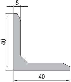 ApplicationsHow to Choose the Right 4040 T-Slot Aluminium Profile for Industrial Applications
 Sourcing and ProcurementPayment Terms for Aluminium Profile Orders (T/T, L/C and the Risk)
 Sourcing and ProcurementAluminium Profile Price Breaks: How Volume Changes the Unit Price
 Sourcing and ProcurementDistributor Terms: Territory, Margin and Price Protection
 Machine SafetyAluminium Profile Machine Guards: Size the Frame from the Energy, Not from the Mesh
