Automation frames · assembly and squaring
Aluminium Profiles for Automation Equipment Frames: Design From the Assembly Floor
A modular frame is not built on the drawing. It is built on the floor, by two people, with a hex key and a tape measure — and that is where frames are lost. Here is the error that grows with length, the squaring sequence, the torque values, the tool clearances, and the six checks that decide whether the machine that arrives on site is the machine that was designed.
Quick answer
- The end face decides the whole member. An end that is 0.2 mm out of square puts the far end of a 2,000 mm member 10 mm out of position, because the error is multiplied by length divided by section width.
- Square the frame before you torque it. Measure both diagonals first, correct them, then torque in a pattern from the most constrained corner, then re-measure. Torquing a skewed frame locks the skew in.
- 1 mm of diagonal difference on a 2,000 mm square frame is 0.35 mrad — about 0.7 mm of skew across the frame. That is the budget you are working to with a tape measure.
- Re-torque after 24 hours and again after the first week. Bolted aluminium joints lose 5 to 10 per cent of their preload to embedment in the first day, and a joint that has relaxed is also a joint that has stopped being conductive.
- Leave 60 mm of clear space at every joint. A 40 series slot takes a 6 mm hex key and a 10 mm socket; an anchor connector needs a drilled hole in the receiving face. Frames that cannot be assembled are designed, not built.
- Four feet is a structure; six feet is an argument. Levelling feet at the posts, castors on a separate base, and never a rigid foot and a castor sharing one member.
Also searched as aluminium profiles for automation frames, automation equipment frame design, aluminium profile machine frame assembly, t-slot frame squaring, aluminium profile torque, modular frame assembly guide.
The error that grows with length
Ask anyone who has built a large modular frame what the hardest part was and they will not say the design. They will say getting it square. The reason is a small geometric effect that is invisible on a short member and enormous on a long one: an end face that is not perpendicular to the profile axis turns the member into a very long lever for its own error.
Why 0.2 mm becomes 10 mm
deviation at the far end = end-face error × length ÷ section widthA 40 mm section, a 2,000 mm member and a 0.2 mm out-of-square end: 0.2 × 2,000 ÷ 40 = 10 mm. The same 0.2 mm on a 200 mm bracket is 1 mm, which is why nobody notices the problem until the frames get big.
| Section width | At 1,000 mm | At 2,000 mm | At 3,000 mm |
|---|---|---|---|
| 40 mm | 5.0 mm | 10.0 mm | 15.0 mm |
| 45 mm | 4.4 mm | 8.9 mm | 13.3 mm |
| 60 mm | 3.3 mm | 6.7 mm | 10.0 mm |
| 90 mm | 2.2 mm | 4.4 mm | 6.7 mm |
The table also explains why a bigger section feels easier to build square, and it is not only because of the width. A larger section usually arrives with a better end, because the cut is made on a bigger machine and the operator can see the error.
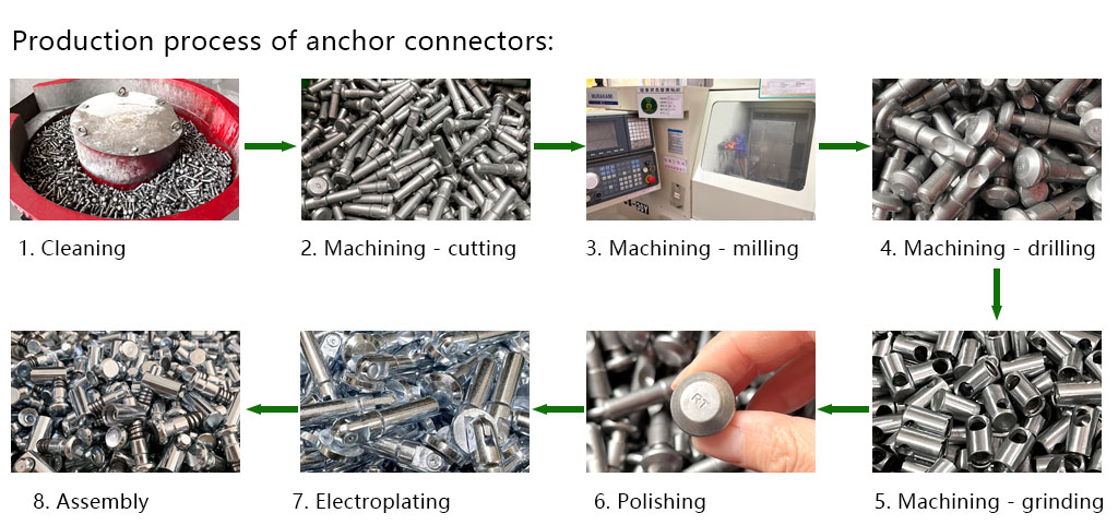
Two ways to remove the problem entirely. The first is to buy the members cut to length with a machined end rather than a mill cut: a mill cut is typically good to about ±1 mm with a burr, a machined end to about ±0.2 mm with a clean square face. The second is to use a connector that references the end face deliberately — an anchor connector is specified with an end-face squareness within 0.2 mm and a hole position within 0.15 mm, so the joint’s own accuracy sets the frame’s accuracy rather than the saw’s.
Square it before you torque it
This is the single biggest procedural difference between a frame that comes out true and one that does not. Torquing a skewed frame does not pull it straight; it locks the skew in and makes it permanent, because every joint is then clamped in a stressed position and the frame will move when the load comes on.
- Assemble finger-tight only. Get every member in place with the bolts just nipping. The frame must still be able to move.
- Put it on a flat surface and check the plane. A frame assembled on an uneven floor will be twisted, and no amount of diagonal measurement will find it. Use a surface plate, a large machined table, or shim the corners until the frame does not rock.
- Measure both diagonals. On a 2,000 mm square frame, the two diagonals should agree within about 1 mm. That corresponds to roughly 0.35 mrad of skew, about 0.7 mm of error across the frame.
- Correct by tapping, not by tightening. Bring the long diagonal in by a light tap at the corner with a soft mallet, then re-measure. Tightening a bolt to pull a frame square works once and then distorts the joint.
- Torque in a pattern, starting at the most constrained corner. Work from the corner where the most members meet outwards, in stages — about half torque first, then full. This lets the frame settle evenly instead of building in a locked-in stress.
- Re-measure the diagonals after torquing, and record them. If the frame has moved, you have found a joint that was not seated. Loosen, reseat, and start again from step three.
The measurement nobody records
Write the two diagonal figures on the frame in marker, with the date. Six months later, when somebody complains that a guard door no longer closes, the difference between the two numbers tells you immediately whether the frame has moved or the door has. It costs nothing and it ends the argument.
Torque, and the twenty-four hour re-check
Torque is a structural number, an electrical number and an assembly-sequence number at the same time, and the values are not interchangeable across series. Using a 40 series torque on a 30 series joint will deform the slot lips; under-torquing a 40 series joint leaves a connection that looks correct and is neither rigid nor conductive.
| Fastener | Slot | Torque | Note |
|---|---|---|---|
| M6 T-nut, 30 series | 8 mm | approx. 6 N·m maximum | Over-torque deforms the slot lips and the nut will no longer seat square |
| M8 T-nut, 40 series | 8 mm | approx. 15 N·m maximum | The standard frame joint; pull-out 1.5 to 2.2 kN per nut |
| M6 square nut, 30 series | 8 mm | 8 – 10 N·m | Larger bearing face than a T-nut; better under vibration |
| M8 square nut, 40 series | 8 mm | 15 – 20 N·m | Preferred where the load reverses |
| M8 subsequent nut, 40 series | 8 mm | 15 – 18 N·m | Fits into an assembled frame, so it is used for late additions |
| M8 anti-torsion nut, 40 series | 8 mm | 15 – 18 N·m | Resists rotation in the slot; use where the joint sees a moment |
Then there is the step almost nobody takes. A bolted aluminium joint loses 5 to 10 per cent of its preload in the first 24 hours to embedment — the microscopic crushing of surface asperities under the nut head and in the thread. The joint has not failed; it has simply settled. But a joint that has settled is also a joint that has loosened, and on a frame that has to be both rigid and electrically continuous, a loose joint is two faults at once.
The re-torque schedule
Torque to specification, then re-torque at 24 hours and again after the first week of operation. After that, spot-check every second joint at each scheduled service. If a joint needs re-torquing repeatedly, the cause is almost always a load that reverses, and the answer is a different fastener rather than a tighter wrench.
Leave access for the tool
A frame that cannot be assembled is not a design, it is a drawing. Every modular joint needs physical room for the tool that will tighten it, and the clearances are set by the slot, not by preference.
The slot sets the key size
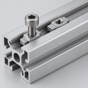
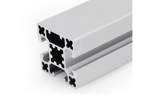
A 40 series profile has an 8 mm slot mouth and takes a 6 mm hex key with a 10 mm socket on the nut. A 60 series with its 10.2 mm mouth takes an 8 mm key. Work out the tool first and the minimum spacing follows.
Anchor connectors need a hole
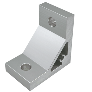
An anchor connector is installed by drilling the receiving face and pulling the connector into the end of the member. That means the receiving face has to be accessible, and it means the machining datum has to be on the drawing before the profile is cut.
Sixty millimetres, as a rule
Do not place two members closer than about 60 mm at a joint. Below that the key cannot swing, the socket cannot seat, and the assembly will be done by improvising with an extension bar and a lot of patience.
Feet, castors and the over-constraint problem
Support layout is where a good frame is quietly ruined, and it is decided by how many feet you fit rather than by how strong they are.
Four feet is statically determinate. The frame sits on three points and rocks onto the fourth when it is loaded. That is correct behaviour: the frame is not being bent by its own supports. Level the four feet, load the frame, and re-check.
Six feet is over-constrained. If the floor is not perfectly flat — and no factory floor is — the extra pair of feet either carries nothing or lifts the frame into a curve. The frame is then pre-loaded in bending before any process load arrives, and the diagonals you carefully set will drift.
| Element | What it is for | Where it goes wrong |
|---|---|---|
| Levelling castor | Moving the frame and then locking it level in place | Used as the only support, so the frame is carried on a swivel with a rubber wheel and never fully settled |
| Swivel foot | Level adjustment on an uneven floor, with a bolt-down option | Fitted mid-span rather than at the posts, adding a point load and a support that will drift |
| Fixed foot | A rigid base at a post where the frame must not move | Mixed with a castor on the same member, so the castor carries nothing until the frame deflects |
| Base plate | Spreading the load at a post and giving a bolting point | Bolted to the floor before the frame is levelled, which pulls the frame into the floor’s shape |
The rule that saves a frame
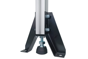
Put the supports at the posts, use four of them for a four-post frame, and if the frame has to be mobile, build a separate base frame that carries the castors. Never mix a rigid foot and a castor on the same member — one of them will be doing nothing, and you will not know which.
Panels, guards and the vibration nobody predicted
Guarding and panels are usually treated as an afterthought, and they are the most common source of noise, rattle and warranty calls on an automation frame. Two rules cover most of it.
Retain the panel along its length, not at its corners. A 4 mm polycarbonate panel bolted only at four corners on a 1,000 mm span will drum at a low frequency, and it will do so intermittently depending on the process. Panel mounting strips in the 8 mm and 10 mm slot sizes spread the retention along the panel edge, which removes the drumming and stops the panel from being a point load on the frame.
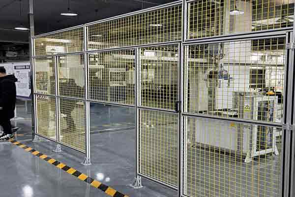
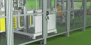
Size the guard frame for the panel, not for the machine. The guard carries the panel’s weight and wind load and the door’s impact, not the machine’s process load. That is usually a much smaller load, and it is why a 30 or 40 series frame is normal for guarding where the machine base is 60 series or larger. The design drivers are the safety distances and the impact resistance, which are set by ISO 14120 and ISO 13857, and the door alignment, which is set by the hinge and the frame squareness you established earlier.
The corollary is worth stating plainly. A guard frame that is 10 mm out of square will show up as a door that catches, a latch that does not engage, and a panel that does not sit flat. The fault will be attributed to the hinges. It is almost always the diagonals.
Robot pedestals: it is rotation, not bolt strength
When a robot is mounted on a modular frame, the conversation usually goes straight to the bolts. That is the wrong first question, though it is not an irrelevant one.
The bolt check. An M8 T-nut in a 40 series slot carries 1.5 to 2.2 kN of pull-out. On a bolt pattern of 400 mm square — eight fasteners at 200 mm from the centre — four of them resist a moment about one axis, giving about 4 × 2 × 0.2 = 1.6 kN·m of resistance. A 6-axis robot with a 1,000 mm reach and a 10 kg payload produces a static moment of roughly 0.1 kN·m from the payload alone, and typically 0.5 to 1 kN·m once the arm mass and a dynamic factor for an emergency stop are included. So the anchorage is adequate, but it is not generous, and it should be checked rather than assumed.
The check that actually decides it. A rotation at the robot base becomes a positioning error at the tool, multiplied by the reach. A base rotation of 0.1 mrad — which is a very small angle, about 0.006 degrees — displaces the tool by 0.1 mm at a 1,000 mm reach. If the robot is specified to ±0.05 mm repeatability, the base has already thrown away the specification before the robot moves.
The design target
Design the pedestal so that its rotation under the worst-case robot moment is no more than about one tenth of the robot’s repeatability at full reach. For a ±0.05 mm robot at 1,000 mm, that is 0.005 mrad — an extremely stiff requirement, and the reason robot pedestals are usually steel, cast iron or a very deep aluminium box rather than a 60 × 60 frame. A modular frame is an excellent robot cell wall; it is rarely a good robot pedestal.
The site acceptance check, in six lines
What to record before the frame is signed off, and what to re-check at the first service. It takes twenty minutes and it converts a set of opinions into a baseline.
| Check | How | Acceptance |
|---|---|---|
| Diagonals | Tape measure, both diagonals, on the largest rectangle in the frame | Within 1 mm on a 2,000 mm frame |
| Plane | Straight edge or a dial gauge across the frame, corner to corner | No rocking, no twist visible |
| Level and feet | Check that every foot is loaded, then re-level | All feet in contact, frame not pre-loaded |
| Torque | Torque wrench on every second joint | At the specified value for the series |
| Guards and doors | Open and close each door, check the latch and the buffer gap | Free movement, latch engages without force |
| Panels | Tap each panel and listen | No drumming; strips along the full edge |
Then write the six results on the frame with the date, and re-run the same six checks at the first service. The value is not the individual numbers — it is the comparison. A frame that has moved 2 mm on its diagonals has told you which joint is failing before it fails completely.
Frequently asked questions
How do I make sure an aluminium profile frame is square?
What torque should I use on aluminium profile joints?
Why does my frame go out of square after a few months?
How much clearance do I need around a joint?
Should I use four or six levelling feet on a frame?
Can a robot be mounted on a modular aluminium frame?
Send the layout and the cut list
We extrude and machine the 20 through 60 series in 6063-T5, cut to length with a machined end where the frame needs it, drill and tap to drawing, and supply the connectors, feet, castors, panel strips and fasteners to match. Send the layout and we will come back with a cut list that can actually be assembled.
Related reading
Twelve more engineering notes from this blog, picked for this article — plus every category below.
 Engineering DesignCustom Aluminium Extrusion: From Drawing to Production
 ApplicationsAluminium Pergola Profiles: A Beam Problem With a Water Problem
 Engineering DesignT-Slot Aluminium: The Slot Mouth Is the Interface Standard, Not the Series Name
 Applications20 Series T-Slot Profiles: Where the Limits Actually Are
 ApplicationsCleanroom and Medical Framing: There Is No Medical-Grade Aluminium Extrusion
 Engineering DesignAluminium Extrusion Die Cost (2026): Price by Section Size
 Engineering DesignAluminum Corner Brackets for T-Slot Frames: How to Choose by Load Path, Not by Looks
 ApplicationsAluminium Profile Display Boards: The Panel Is the Hard Part
 Quality and InspectionGlobal Sourcing Excellence: Multi-Category OEM and ODM Manufacturing and Supply Chain Integration
 Materials and EngineeringIndustrial Aluminum Profiles: Alloys, Tempers and How to Select Them
- Materials and Engineering6063-T5 Aluminium Profile: What the Designation Actually Guarantees
 Sourcing and ProcurementPayment Terms for Aluminium Profile Orders (T/T, L/C and the Risk)
