Aluminium Profiles in Solar Mounting: Wind Uplift, Corrosion and a 25-Year Life
A solar mounting structure is asked to survive a quarter of a century outdoors with essentially no maintenance. That single fact changes every decision in the specification, and it rules out several choices that would be perfectly reasonable in a machine frame.
Short answer
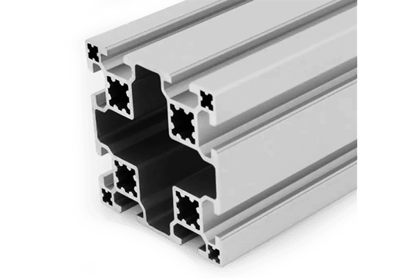
Solar mounting profiles are governed by a 25-year outdoor design life, and three consequences follow. Wind loading is usually governed by uplift rather than downward pressure, because a tilted panel behaves like a wing. Corrosion control has to cover the galvanic couple between the aluminium and its stainless fasteners in rainwater. And because an anodic layer is electrically insulating, the earth bonding path across the structure cannot be assumed — it has to be detailed. Section size follows from the wind case and the span, both of which come from the site.
A quarter of a century changes the question
Most aluminium structures are designed for a machine that will be modified, moved or replaced within a decade, and maintained in the meantime. A solar mounting structure has none of those escape routes. It is expected to stay outside, unattended, for a design life commonly taken as 25 years.
That reframes the specification. Decisions that would be marginal in a machine frame become consequential here, because there is no scheduled re-tightening, no repainting and no convenient replacement. A coating choice, a fastener material or a joint detail that would survive ten years of industrial service can fail well short of 25 years of weather.
It also means the specification has to be about degradation mechanisms rather than about initial strength. The mounting structure is rarely close to its load capacity. It is far more likely to be limited by corrosion, by loosening, or by the slow loss of a protective layer.
On the load figures
Wind and snow actions for a specific installation come from the site’s wind and snow zone and the code that applies there. This article explains which cases govern and why; the values have to be taken from the applicable standard for the location.
Wind: the governing case pulls up
The intuitive picture of wind loading is pressure pushing down on a panel. The governing case is usually the opposite.
A tilted panel behaves like an aerofoil in a flowing airstream: flow accelerates over the upper surface, pressure there drops, and the result is a net force that lifts. Uplift is frequently larger in magnitude than the downward pressure case, and it acts on a structure whose resistance comes from its own weight and its anchorage rather than from the ground beneath it.
That has two consequences for an aluminium structure. The first is that the anchorage governs: the fixing into the roof or the ground has to resist a sustained, reversing, cyclic pull-out load for 25 years. The second is that fatigue enters, because the load cycles with every gust. A structure sized only for the static downward case will be under-designed for the case that actually occurs.
| Load case | Direction | What resists it | Why it matters |
|---|---|---|---|
| Dead load | Down | Structure and supports | Known, small, constant |
| Wind pressure | Down | Structure and supports | Usually not the governing case |
| Wind uplift | Up | Anchorage and self weight | Often governs, and it is cyclic |
| Snow | Down | Structure | Regional; combines with wind |
| Thermal movement | Along the array | Expansion provision | Long rows need room to move |
The earth path is not automatic
This is the detail that catches aluminium mounting structures out, and it is a direct consequence of the finish that makes aluminium suitable for outdoor use.
Panel frames and the mounting structure are required to be at the same electrical potential, and the array has to be bonded to earth. With steel, that happens largely by itself: bolted steel-to-steel contact conducts. With anodised aluminium, it does not. An anodic oxide layer is an electrical insulator, and two anodised parts bolted together are separated by a non-conducting film on both sides.
The result is a structure that looks continuous and is not. Bonding has to be deliberate: a toothed or serrated washer that cuts through the layer at the joint, a designated bonding point with the coating removed, or a separate bonding conductor. Which method is used has to be stated, and it has to be one that still works after 25 years of weathering.
- Anodic layer on both mating faces
- Powder coat on the contact area
- An isolation washer fitted without thought
- Corrosion product building up in the joint
- Serrated or toothed washers that cut through the film
- Designated bonding points with coating removed
- A dedicated bonding conductor across joints
- A stated test method to verify continuity
Galvanic corrosion: the couple you create by choosing stainless
The natural instinct for a 25-year outdoor structure is to specify stainless fasteners. That is usually right, and it creates a problem that has to be managed.
Aluminium and stainless steel are far apart in the galvanic series. Join them electrically, add rainwater — which is a perfectly good electrolyte — and the aluminium corrodes to protect the stainless. The bolt stays bright and the hole around it disappears, which is the worst kind of failure because it is invisible until something moves.
The controls are standard and they have to be specified rather than assumed: isolate the two metals where practical, keep the cathodic area small relative to the anodic one, exclude water from the joint, and specify a coating on the aluminium. Where isolation is used, remember the conflict with the previous section: an isolation washer helps corrosion and breaks the earth path, so the bonding has to be provided separately.
CONTROL 1
Isolate the metals. Sleeves, washers or coatings at the contact — and bond separately.
CONTROL 2
Keep water out. Seal the joint so the electrolyte is not present.
CONTROL 3
Specify the coating. A thickness class, not a process name, and seal cut ends.
CONTROL 4
Check the area ratio. Small cathode, large anode is the safe direction.
Thermal movement along a long row
Aluminium expands measurably with temperature, and a solar array is a structure that sees the full range: cold nights, hot days, and direct sun on dark surfaces that raises the metal well above air temperature.
A short array can absorb this. A long row cannot. Over tens of metres the total movement is substantial, and if the structure is restrained at both ends it will either bow or transfer the load into the anchorage. Long rows need provision for the movement, either through expansion joints in the rail run or through fixings that permit sliding.
The same reasoning applies to the anchorage spacing. Fixing points that are too close together over-constrain the run; too far apart and the rail lacks support. The arrangement follows from the movement range as well as from the load, and it is worth stating on the drawing so it is not decided on the roof.
What to send with a solar mounting enquiry
Solar enquiries are unusually specific, because the load depends entirely on the site. Six items, and the ones most often missing are the site data and the bonding method.
RFQ checklist — solar mounting profiles
- Site wind and snow zone — the load cannot be derived without it; state the code used.
- Tilt angle and array layout — they set the uplift coefficient and the row length.
- Panel dimensions and weight — and the mounting hole positions on the frame.
- Rail span and support spacing — the span governs the section as much as the load does.
- Mounting surface — pitched roof, flat roof or ground; it drives the anchorage entirely.
- Corrosion environment — inland, coastal or industrial; it sets the coating class and the fastener material.
- Bonding and earthing method — state it; an anodised joint does not bond by itself.
- Design life and standard — 25 years is usual; name the standard the design follows.
Ask how the earth continuity is achieved and how it is verified. If the answer is that it happens through the bolted joints, the coating has not been considered.
Four ways a mounting structure fails early
Related on this site
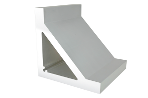
- Aluminium angle profiles— cleats and connection trim for mounting
- PG40 80 x 40 six-slot heavy profile— a rail section for longer spans
- Strut profiles category— the structural section range
- Industrial vs construction acceptance— why outdoor work is checked differently
Terms used in this article
- Uplift
- A net upward wind force on a tilted surface, caused by reduced pressure on its upper face.
- Galvanic couple
- Two dissimilar metals electrically connected in an electrolyte; the more anodic one corrodes.
- Bonding
- Establishing an intentional electrical connection between conductive parts.
- Anodic layer
- The aluminium oxide coating produced by anodising; hard and corrosion resistant, but electrically insulating.
- Expansion provision
- Design allowance for a structure to change length with temperature without damage.
- Cyclic load
- A load that repeats, such as wind gusting; brings fatigue into the design.
Questions buyers ask
Is the wind case pushing down or pulling up?
Usually pulling up. A tilted panel behaves like a wing, so the governing case is often uplift, resisted by the anchorage and the structure’s own weight. It is also cyclic, so fatigue matters.
Do I need to worry about earthing with anodised profile?
Yes, and this is the most commonly missed item. An anodic layer is an insulator, so bolted anodised joints are not electrically continuous. Specify a bonding method and how it will be verified.
Which fasteners for an outdoor array?
Stainless is common, but it forms a galvanic couple with aluminium in rainwater. Use isolation, seal the joint, specify the coating class, and provide bonding separately because isolation breaks the earth path.
How long can a rail run be before thermal movement matters?
It depends on the temperature range and the restraint arrangement rather than on a fixed length. As a rule, long rows need deliberate expansion provision; short arrays can usually absorb the movement.
What coating class for a coastal site?
Coastal and industrial exposure need a thicker anodic class or a suitable coating system, with sealed cut ends. Discuss the alloy and the coating together, and expect the fastener material to matter as much as the profile.
Send the site zone and the array layout
Give us the wind and snow zone, the tilt and the row length, and we will size the rail and specify the coating, bonding and fastener plan for 25 years.
Request a quoteRelated reading
Twelve more engineering notes from this blog, picked for this article — plus every category below.
 ApplicationsAluminium Conveyor Frames: Why Belt Tracking Is a Geometry Problem
 ApplicationsAluminium Profiles in Industry and Construction: One Material, Two Acceptance Logics
 Materials and EngineeringRecycled Aluminium Profiles: A Number You Have to Be Able to Evidence
 ApplicationsAluminium Profile Display Boards: The Panel Is the Hard Part
 Engineering DesignHow to Choose the Right Aluminium Profile Size for Industrial Frames
 Materials and EngineeringAluminium Corrosion: Why a Salt Spray Number Is a Ranking, Not a Life
 ApplicationsHow to Fix Panels, Guards and Accessories to Aluminium Profiles
 Materials and EngineeringIndustrial Aluminium Extrusion: Five Advantages and the Conditions Attached to Each
 Sourcing and ProcurementPayment Terms for Aluminium Profile Orders (T/T, L/C and the Risk)
 Engineering DesignAluminium Profile Anchor Pins: A Preloaded Joint, Not a Pin
 Engineering DesignStandard vs Custom Aluminium Extrusion: The Break-Even Calculation
 Engineering DesignHow to Choose the Right T-Slot Aluminium Profile for Your Project
