Strength and support conditions
How Strong Is an Aluminium Profile? It Depends on How You Fix It
Ask a supplier for a load rating and you will get a number that quietly assumes a support condition nobody mentioned. The same 40 × 40 section carries 6.6 kg as a cantilever and 206 kg between two fixed ends. Here is the ladder, the formula behind it, and the point at which the joint takes over from the profile.
Quick answer
- There is no single load rating for an aluminium profile. A rating only means something once four things are fixed: the span, the support condition, the deflection limit and the safety factor. None of the four appear on a profile datasheet.
- Take a 40 × 40 standard section with a second moment of area of 9.2 cm⁴, a 1,000 mm span, a safety factor of 2 on yield and a deflection limit of L/300. It carries 6.6 kg as a cantilever, 103 kg simply supported, 138 kg with one end fixed and 206 kg with both ends fixed. Same metal, same length: a 31× spread.
- That spread comes entirely from the support condition. In δ = F L³ ÷ (k E I) the coefficient k is 3 for a load at a cantilever tip, 48 for a mid-span load on a simply supported beam, 110 for one end fixed and 192 for both ends fixed.
- Span enters cubed. Doubling the span does not halve the capacity — with a fixed deflection limit in millimetres it cuts it to one eighth, and even with a limit that scales with span such as L/300 it still cuts it to one quarter.
- Two failure modes compete, and the winner changes with span. A simply supported 40 × 40 is yield-limited below about 1,020 mm and deflection-limited above it. A cantilever crosses over at about 255 mm, which is why almost every real cantilever is deflection-limited.
- The connection normally gives up first. A T-slot nut has a recommended design pull-out value of 7.2 kN per fastener, and an M8 fastener holds about 2,100 N in friction. A bracket that relies on friction alone can slip long before the profile reaches its own limit.
Also searched as: how much weight can aluminium profile hold, aluminium profile load capacity, is aluminium profile strong enough, T-slot profile weight limit, aluminium extrusion strength compared with steel, 4040 profile maximum load.
One profile, four answers
Everything below uses one section, one span and one set of design criteria, so the only variable is where the ends are held. The section is a 40 × 40 standard T-slot profile: I = 9.2 cm⁴ (92,000 mm⁴), section modulus Z = 4.6 cm³ (4,600 mm³) about the bending axis. The span is 1,000 mm. The material is 6063-T5 with a minimum 0.2 per cent proof stress of 110 MPa, halved to an allowable 55 MPa by a safety factor of 2. The deflection limit is span/300, so 3.33 mm.
| Support condition | k in F = k E I δ ÷ L³ | Yield limit | Deflection limit | Governing load |
|---|---|---|---|---|
| Cantilever, load at the free end | 3 | 26 kg | 6.6 kg | 6.6 kg |
| Simply supported, load at mid-span | 48 | 103 kg | 105 kg | 103 kg |
| One end fixed, one end simply supported | 110 | 138 kg | 240 kg | 138 kg |
| Both ends fixed against rotation | 192 | 206 kg | 420 kg | 206 kg |
Read the last column as a ladder. Nothing about the profile changed between the rows. The cantilever carries 6.6 kg, the fixed-fixed beam carries 206 kg, and the ratio is 31 to one. On pure deflection the raw ratio is 64 to one, because the k coefficients go from 3 to 192.
Governing load, 40 × 40 standard, 1,000 mm span
Only the end conditions changed between these four bars.
The first bar is not a rounding error. A metre-long cantilever of 40 × 40 is a genuinely weak element, and the reason is not the aluminium — it is that a cantilever concentrates all of its bending at one end and has no second support to share the deflection.
One caveat on the fixed-end rows. The coefficients 110 and 192 assume the ends are genuinely restrained against rotation. In a bolted T-slot frame that assumption is usually false. A standard die-cast corner bracket with two bolts does not stop the joint rotating; it only resists it. Unless you have gussets, heavy joining plates or a welded joint, the honest design assumption for a bolted frame is somewhere between simply supported and semi-rigid. Design to 48 and you will not be surprised.
The formula, and why span is the strongest lever
Every number in the previous table comes from one equation. The only thing that changes between support conditions is the coefficient in front of it.
δ = F × L³ ÷ (k × E × I)
δ is the deflection in mm, F the load in N, L the span in mm, E the modulus of elasticity in N/mm² (70,000 for any 6xxx alloy, whatever the temper), I the second moment of area in mm⁴, and k the support coefficient. To get a load rather than a deflection, rearrange to F = k E I δ ÷ L³.
The span appears three times, and it is not inside the coefficient. That asymmetry is why the practical answer to “how strong is this profile” is almost never “change the profile”. Shorten the span and you win on all three counts at once.
A cantilever is worse than it looks
Designers routinely underestimate cantilevers because they compare the length to a simply supported span of the same length. They are not equivalent. Set the cantilever deflection equal to the simply supported deflection and solve for the span that produces the same movement:
L³ ÷ 3 = s³ ÷ 48 → s = 2.52 L
A cantilever of length L deflects as much as a simply supported beam of span 2.5 L. A 400 mm cantilever is not a short beam; it behaves like a one metre span. This single ratio explains most of the surprise calls we get about overhanging brackets and side-mounted rails.
The span table
Same 40 × 40 standard section, simply supported, load at mid-span, same safety factor of 2 and the same span/300 deflection limit. Only the span changes.
| Span | Deflection limit | Yield-limited load | Deflection-limited load | Governing |
|---|---|---|---|---|
| 500 mm | 1.67 mm | 206 kg | 420 kg | 206 kg, yield |
| 750 mm | 2.50 mm | 138 kg | 187 kg | 138 kg, yield |
| 1,000 mm | 3.33 mm | 103 kg | 105 kg | 103 kg, yield |
| 1,250 mm | 4.17 mm | 83 kg | 67 kg | 67 kg, deflection |
| 1,500 mm | 5.00 mm | 69 kg | 47 kg | 47 kg, deflection |
| 2,000 mm | 6.67 mm | 52 kg | 26 kg | 26 kg, deflection |
Go from 500 mm to 2,000 mm and the yield-limited load falls by a factor of four, because bending moment is linear in span. The deflection-limited load falls by a factor of sixteen, because it is governed by span squared once the deflection limit is written as a fraction of span. That difference is the whole story of the table: short spans are limited by the strength of the metal, long spans by its stiffness.
Where the limit actually sits
Two equations compete, and the one that produces the smaller load governs. Written for a simply supported beam with a mid-span load:
- Yield: F = 4 Z σ ÷ L, where Z is the section modulus and σ the allowable stress.
- Deflection: F = 48 E I δ ÷ L³. With the limit set to L/300 this simplifies to F = 0.16 E I ÷ L².
Set them equal and the span at which the governing criterion switches falls out directly:
Lcrossover = 0.04 × E × I ÷ (Z × σ)
For the 40 × 40 standard section with σ = 55 MPa this gives 1,018 mm. For the same section as a cantilever the coefficient becomes 0.01 instead of 0.04, and the crossover drops to 255 mm.
| Support condition | Crossover span | Below the crossover | Above the crossover |
|---|---|---|---|
| Cantilever, tip load | 255 mm | yield-limited | deflection-limited |
| Simply supported, mid-span load | 1,018 mm | yield-limited | deflection-limited |
Two consequences follow, and both of them contradict the way profiles are usually specified.
Almost every cantilever is deflection-limited. A 255 mm crossover is shorter than nearly any real overhang, so a cantilever is nearly always limited by how far it sags, not by how much it can carry before it bends permanently. Buying a higher-strength alloy for a cantilever buys nothing at all.
A stronger alloy moves the crossover down, not up. The crossover is inversely proportional to allowable stress. Replace 6063-T5 with 6061-T6 and the allowable stress roughly doubles from 55 to 138 MPa, so the crossover for a simply supported 40 × 40 falls from 1,018 mm to about 406 mm. The stronger alloy does not extend the range in which strength matters — it shrinks it. Above 406 mm the frame is stiffness-limited, and stiffness does not care what alloy you bought.
Why this is the most useful number in the article. If you know the crossover span for your section and your support condition, you know which lever to pull. Below the crossover, change the alloy, the wall thickness or the section. Above it, change the span, add a support, or accept a bigger deflection. Most overspecified frames we see were overspecified because the designer pulled the wrong lever.
What actually makes a frame stronger
This is the comparison that decides real projects. Baseline is the 40 × 40 standard section in 6063-T5, simply supported, 1,000 mm span, safety factor 2, deflection limit L/300. Every row changes one thing.
| Change made | I | Governing load | Gain | What it costs |
|---|---|---|---|---|
| Nothing — 40 × 40 standard, 6063-T5 | 9.2 cm⁴ | 103 kg | — | baseline |
| Stronger alloy — 6061-T6 | 9.2 cm⁴ | 105 kg | 1.02× | higher metal price, no usable gain |
| Heavier wall — 40 × 40 heavy | 12.4 cm⁴ | 139 kg | 1.35× | +35 per cent weight per metre |
| Larger section — 45 × 45 standard | 15.5 cm⁴ | 155 kg | 1.50× | more material, larger footprint |
| Larger section — 60 × 60 standard | 26 cm⁴ | 194 kg | 1.88× | much more material, bulkier frame |
| One extra support — two 500 mm spans | 9.2 cm⁴ | 412 kg | 4.00× | one bracket and one upright |
The bottom row is not a mistake, and it is the most important row in this article. Adding a single mid-support halves the span twice over, and the two short spans each carry 206 kg, so the assembly carries 412 kg using exactly the same profile as the baseline. One extra support outperforms every material and section change on the list, by a factor of two over the largest section available.
If you take one design rule away from this page, take this one: before you open the profile catalogue, count your supports. The difference between a 1,000 mm unsupported span and two 500 mm spans is larger than the difference between a 40 × 40 and a 60 × 60.
The joint gives up before the profile does
Every number so far assumed the ends do what the theory says. In a bolted T-slot frame that is the least reliable part of the calculation, and it is where most real failures start.
Two joint types, one order of magnitude apart
There are two ways to connect a horizontal member to a vertical one, and they behave completely differently.
- Reaction-force joint. The horizontal profile rests on top of the vertical one, so the load travels directly through metal-to-metal contact. This is the strong configuration and it should be the default wherever the layout allows it.
- Friction-only joint. A plate is bolted to the side of the vertical profile and the horizontal member hangs off it. The load now depends entirely on the clamping force of the bolts and the friction between the surfaces. This is the weak configuration, and it is the one people build when they want a flush face.
The published design values make the gap concrete. Each M8 fastener tightened to 13 N·m generates about 2,100 N of friction, so a six-fastener plate can hold roughly 12,600 N in a friction joint — but only if every bolt is correctly torqued. A reaction-force joint does not depend on torque at all.
The pull-out value, and the number you should actually use
| Fastener pull-out, per fastener | Value | How to use it |
|---|---|---|
| Ultimate strength, standard extrusion | 16.7 kN | never design to this; the extrusion is already damaged |
| Recommended design value, standard extrusion | 7.2 kN | below the material yield point, no permanent deformation |
| Recommended design value, light-wall extrusion | 3.5 kN | light sections are not for critical structural joints |
| Friction per M8 fastener at 13 N·m | 2,100 N | friction-only joints only |
Do not design to the ultimate value. The ultimate pull-out strength is the point at which the slot lip tears out of the profile. By then the extrusion is scrap. The design value is set below the material yield point precisely so that the joint can be overloaded, inspected and re-tightened without permanent damage. If a drawing quotes the ultimate number as a working load, that drawing is wrong.
Checking a real cantilever
Return to the 6.6 kg cantilever from the first table — a 40 × 40 standard section overhanging 1,000 mm with the load at the tip. The bending moment at the root is 6.6 kg × 9.81 × 1,000 mm, which is 64,700 N·mm, or 64.7 N·m. Two questions follow.
Will the bracket slip? Assume a two-bolt bracket with the fastener line about 20 mm from the profile axis. The slip resistance is 2 × 2,100 N = 4,200 N, and the resisting moment is 4,200 N × 20 mm = 84,000 N·mm = 84 N·m. That is above the 64.7 N·m required, so a two-bolt friction joint just holds. Reduce it to a single bolt and the resisting moment falls to 42 N·m, which is reached by a 4.3 kg tip load — below the 6.6 kg the profile itself can take. The single-bolt bracket is the weak link, not the profile.
Will the fastener pull out? The same moment divided by the 28 mm spacing between the two fasteners gives a tensile force of 64,700 ÷ 28 = 2,310 N per fastener, or 2.3 kN. Against a 7.2 kN design value that is 32 per cent utilisation. Pull-out is not the problem. Friction is.
The practical conclusion. On a bolted frame, the failure sequence runs joint first, deflection second, material last. That is the reverse of the order in which most designers make decisions. Check the joint configuration and the bolt count before you spend money on a bigger section or a stronger alloy.
Safety factors, chosen by consequence
A safety factor is not a measure of how much you distrust the supplier. It covers the load you did not know about, the calculation you simplified and the consequence of being wrong. Choose it from what happens if the frame fails.
| Application | Safety factor on yield | Why this value |
|---|---|---|
| Display frame, static load, nothing under it | 2.0 | the load is known and failure is cosmetic |
| Workbench or assembly table | 2.5 – 3.0 | load varies, people lean and climb on it |
| Machine guard or equipment enclosure | 3.0 – 4.0 | vibration, dynamic peaks, moving parts |
| Gantry beam, robot axis, moving mass | 4.0 – 5.0 | acceleration and reversal multiply the static load |
| Personnel protection, overhead load, walkway | 5.0 and above | failure means injury, not a repair |
Apply the factor to your least certain input, not to your best estimate. If you are unsure whether the load is 200 kg or 300 kg, apply the factor to 300 kg and then add margin for the uncertainty itself.
The safety factor and the deflection limit are two separate checks. A frame can be perfectly safe and still unusable. If a beam is strong enough at 5× the load but sags 3 mm under the tool, it is a failed design that will never fail structurally. Decide the deflection limit first — 0.1 mm for metrology, 0.5 mm for a machine tool axis, 1 to 3 mm for a workstation, more for a guard — and let the strength check confirm that you are not also overloading the metal.
Frequently asked questions
How much weight can a 40 × 40 aluminium profile hold?
It depends entirely on the span and the support condition, and the spread is large. With a safety factor of 2, a deflection limit of span/300 and a 1,000 mm span, a 40 × 40 standard section in 6063-T5 holds about 103 kg simply supported with the load at mid-span, about 138 kg with one end fixed, about 206 kg with both ends fixed, and only about 6.6 kg as a cantilever with the load at the free end. If you need one number to remember, remember 103 kg for the simply supported case, and remember that shortening the span to 500 mm doubles it.
Is aluminium profile as strong as steel?
Per kilogram, yes — and for stiffness per kilogram it is better. Aluminium has a modulus of about 70 GPa against 200 GPa for steel, but it is also about one third the density, so a stiffness-matched aluminium section weighs roughly half as much as the steel one. What aluminium loses is absolute strength per unit of cross-section: the yield strength of 6063-T5 is 110 MPa against 235 MPa or more for structural steel. That means an aluminium beam of the same external dimensions as a steel beam will deflect about three times as much and yield at a lower load. The comparison only favours aluminium when you are free to make the section deeper, which is why aluminium frames use large, thin-walled sections rather than solid bars.
Does a thicker wall make the frame much stronger?
Less than most people expect. Going from the 40 × 40 standard wall to the heavy wall raises the second moment of area from 9.2 to 12.4 cm⁴, which raises the governing load from 103 kg to 139 kg at a 1,000 mm span. That is a 35 per cent gain for roughly 35 per cent more weight per metre. The geometry of a square section is dominated by its outer dimension, not its wall. Moving from 40 × 40 standard to 45 × 45 standard gives a 50 per cent gain for a similar material increase, and 60 × 60 gives 88 per cent. If you are going to add metal, add it at the outside.
Why does my frame bend more than the calculation said?
Four usual causes, in order of likelihood. First, the end conditions are not what you assumed: a bolted corner bracket rotates, so the real behaviour is closer to simply supported than to fixed. Second, the load is not a clean point load at mid-span — an offset load, a moment, or a load applied through a bracket changes the moment distribution. Third, the connection is slipping: a friction joint that moves under load adds deflection that no beam equation predicts. Fourth, the load is dynamic. A moving mass accelerating and reversing can put several times the static load into the frame, which is why gantry beams and robot axes use a safety factor of 4 to 5 rather than 2.
Is a welded frame stronger than a bolted T-slot frame?
Yes, if the joints are the limitation, and on a bolted frame they usually are. A welded corner transmits moment, which lets you claim the fixed-end coefficients of 110 or 192 instead of 48. A bolted corner bracket does not, so the honest assumption is closer to simply supported. But welding costs you the two things T-slot is bought for: adjustability and a clean anodised finish. The practical middle route is to keep the bolted frame and make the joints stiffer with heavy joining plates, gussets and reaction-force rather than friction-only joints, then design to the simply supported coefficients and treat any extra fixity as unearned margin.
What deflection limit should I design to?
Set it from what the frame has to do, not from a generic rule. For metrology fixtures, optical mounts and anything carrying a measuring head, keep the movement under 0.1 mm. For machine tool axes and linear motion, 0.2 to 0.5 mm is typical. For workstations, benches and general equipment frames, 1 to 3 mm is normally acceptable, and span/300 is a reasonable default that lands inside that band for spans between 300 mm and 900 mm. For machine guards, display frames and anything purely protective, 5 mm or span/200 is usually fine. Write the limit on the drawing before you select the profile, because the limit, not the load, is what selects the section in most long-span frames.
Tell us the span and the support condition
Send us the layout, the load and the deflection limit you need. We will come back with the section, the wall thickness and the joint configuration that meets it, together with the calculation so you can check it.
Related reading
Twelve more engineering notes from this blog, picked for this article — plus every category below.
 ApplicationsAluminium Profiles in Solar Mounting: Wind Uplift, Corrosion and a 25-Year Life
 Engineering DesignMetric vs Imperial T-Slot Profiles: How to Test Compatibility Before You Order
 Engineering DesignWhat Is a 2020 Aluminium Profile? (Weight, Slot and Load)
 Engineering DesignWhat Your Extrusion Drawing Must Show (and What Costs You Money)
- Engineering Design2020 vs 3030 Aluminium Profile: Which for Your Frame
 ApplicationsWhere Modular Aluminium Framing Works: A Load-Tier Map Instead of an Industry List
 ApplicationsAluminium Conveyor Frames: Why Belt Tracking Is a Geometry Problem
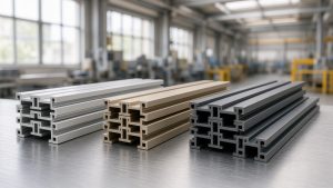 Engineering Design6063 vs 6061 vs 6082 and T5 vs T6: What Changes in Practice
 Quality and InspectionGlobal Sourcing Excellence: Multi-Category OEM and ODM Manufacturing and Supply Chain Integration
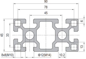 Materials and EngineeringAluminium Extrusion Section Design: What Each Feature on the Drawing Costs You
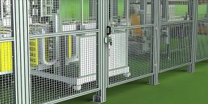
 Machine SafetyAluminium Profile Machine Guards: Size the Frame from the Energy, Not from the Mesh
 Materials and Engineering6063-T5 Aluminium Profile: What the Designation Actually Guarantees
