Where Modular Aluminium Framing Works: A Load-Tier Map Instead of an Industry List
Most guides list industries. That is the wrong axis, because one industry contains both a 3 kg display stand and a 3 tonne gantry. The section you need is set by load, span and environment — not by the sector on the purchase order.
Short answer
Classify the application by load per node and unsupported span, then pick the series from the tier table: 20 series for under 10 kg per node, 30 or light 40 for 10–100 kg, standard 40 series for 100–500 kg, 40x80 or 45x90 heavy sections for 500–2000 kg, and 80x120 or steel above that or beyond a 4 m span. In nearly every tier the governing limit is deflection, not yield strength, so the tier is really set by how much sag the application tolerates.
Why an industry list cannot tell you the section
“Aluminium profiles are used in automation, automotive, electronics, food processing, construction and furniture” is a true sentence and a useless specification. Inside the electronics sector alone there is a 2 kg test jig and a 1.5 tonne panel-handling gantry, and they share no structural requirement whatsoever.
What actually varies between applications is three quantities: the load arriving at a single joint, the distance a member spans without support, and how much deflection the function tolerates before it stops working. Industry names are a proxy for these three, and a poor one, because they also carry environmental expectations that have nothing to do with load.
So the useful move is to separate the two. Decide the tier from load and span first, then apply environment as a modifier to the surface finish, the alloy and the hardware material. Two applications in different sectors that land in the same tier will use the same section and differ only in finish.
The check that exposes a mis-tiered design
If two engineers independently size the same frame and arrive at sections two series apart, the disagreement is almost never about strength. It is about an unstated deflection limit. Write the number down before anyone sizes anything.
The five tiers
The table below is a starting point, not a substitution for calculation. It exists to get a project into the right neighbourhood in one pass so that the detailed check starts from a sensible section instead of from guesswork. Load is given per node, which is the number that matters, because a frame rarely fails in the middle of a member — it fails where members meet.
| Tier | Load per node | Typical span | Series | Slot / fastener | Deflection limit |
|---|---|---|---|---|---|
| 0 — Display | Up to 10 kg | Under 1 m | 20 series, 20x20 | 6.2 mm groove, M5 | L/150 |
| 1 — Light duty | 10–100 kg | 1–1.5 m | 30 series or light 40 | 8 mm mouth, M6 | L/200 |
| 2 — Machine frame | 100–500 kg | 1.5–2.5 m | 40 series, 40x40 heavy | 10.2 mm groove, M8 | L/300 |
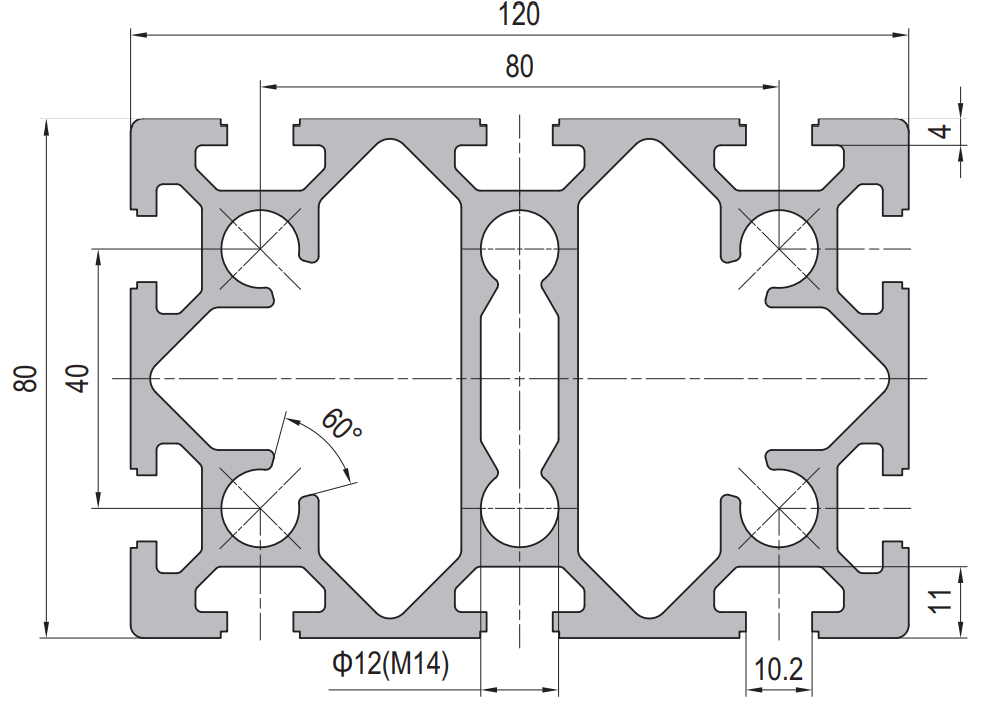
| 3 — Heavy duty | 500–2000 kg | 2.5–4 m | 40x80 or 45x90 | 10.2 mm groove, M8/M10 | L/500 |
| 4 — Structural | Over 2000 kg | Over 4 m | 80x120, or steel | M10 and machined nodes | By calculation |
Two boundaries in that table are worth more attention than the rest. The jump from tier 1 to tier 2 is where M6 hardware runs out and the whole fastener inventory changes, so crossing it late in a project is expensive. The jump from tier 3 to tier 4 is where aluminium stops being the obvious answer, and it is the boundary most often crossed by accident.
What changes inside the joint as the tier rises
The section size is the visible change. The invisible one is the connector class, and it is the one that decides whether a tier-3 frame actually delivers tier-3 performance.
At tier 0 and 1, external brackets and plastic or nylon corner pieces are adequate, because the moment at the node is small enough that the bracket’s own stiffness is not the limiting factor. At tier 2 the joint has to carry a real moment, and a die-cast bracket plus a properly torqued M8 becomes the minimum. At tier 3, external brackets start to be the compliant element in the frame, and internal connections — end-tapped holes with bolts through the section — take over, sometimes backed by an external plate.
TIER 0–1
External brackets. Corner pieces and light brackets. Fast and reconfigurable; joint stiffness is not yet critical.
TIER 2
Die-cast bracket + M8. The node now carries moment. Torque values matter for the first time.
TIER 3
Internal connection. End-tapped sections with through bolts. Bracket compliance is now the weak link.
TIER 4
Machined node or steel. Purpose-designed joint, or the frame stops being aluminium.
This progression is why a frame that “looks strong enough” still racks under load. The members are fine; the joints are the springs. If a tier-3 frame is built with tier-1 connectors, the deflection will be several times the calculated value regardless of how heavy the section is.
Environment as a modifier, not a tier
Environment does not change the section. It changes the alloy, the finish and the hardware material, and it is applied after the tier is fixed. Treating environment as a separate axis stops one common failure: specifying a heavier section to solve a corrosion problem that a heavier section does not touch.
| Environment | What actually degrades | The specification change |
|---|---|---|
| Washdown, food, chemical | Fasteners and cut ends corrode first | Stainless fasteners, sealed cut ends, deeper anodising |
| Clean room, medical | Exposed grooves trap contamination | Rounded sections, groove covers, flush panel infill |
| Electronics assembly | Anodised layer insulates the frame | ESD path engineered across joints, not assumed |
| Outdoor, coastal | Pitting at machined holes and edges | 6061 rather than 6063, thicker anodic layer, sealed machining |
| Elevated temperature | Preload relaxes, aluminium expands 23 µm/m·K | Allow for expansion, re-check torque, avoid over-constraint |
Note that none of those rows asks for a bigger section. A washdown frame does not need more metal; it needs the right fastener metallurgy and a cut end that is not an open channel into the section.
Six questions that turn an application into a specification
When an enquiry says “we need a frame for a packaging machine”, the supplier cannot quote, because none of the three governing quantities is present. These six questions produce them in about fifteen minutes, and they are the same six whether the frame is a bench or a gantry.
RFQ checklist — turning an application into a spec
Answer these before the enquiry goes out:
- What is the heaviest single load, and where does it sit? Peak load at one point, not total weight.
- What is the longest unsupported span? This sets the tier more often than the load does.
- How much sag can the function tolerate? State it as a fraction of span, or name the consequence that defines it.
- Is the frame static, or does it move? Motion brings fatigue and vibration loosening, which changes the connector class.
- What environment does it sit in? Washdown, clean room, outdoor, ESD, temperature range.
- Will it be modified? If yes, the connector class goes up and the section choice narrows to a standard series.
The answer to the third question is the one most often missing, and it is the one that decides the tier. A frame for a display tolerates visible sag; a frame carrying a linear rail does not.
Four ways the tier gets picked wrong
Checks before releasing the drawing
- State the deflection limit on the drawing, in writing, next to the load case.
- Confirm the connector class matches the tier, not just the section size.
- Check that the longest span in the model is the one that was calculated.
- Confirm every node has a defined connector, drawn or scheduled.
- Re-read the environment row against the finish and fastener callouts.
Related on this site
- PG40 80 x 40 six-slot heavy profile— the tier 3 beam section
- PG45 90 x 45 six-slot heavy profile— the alternative tier 3 section with a wider mouth
- 40 series aluminium profiles— the series most tier 2 frames converge on
- Profile sizes 20 x 20 to 100 x 100: what fails first— which limit arrives first as sections grow
Terms used in this article
- Load per node
- The force arriving at a single joint, as distinct from the total weight of the assembly.
- Deflection limit
- The maximum sag the function tolerates, usually expressed as a fraction of the span such as L/300.
- Connector class
- The load-carrying capability of the joining hardware, independent of the section size.
- Racking
- Loss of squareness in a frame under load, caused by joint compliance rather than member bending.
- Tier
- A load-and-span band that maps to a series and a connector class.
Questions buyers ask
Can I use 40 series for everything and just add more of it?
For tier 1 and 2, often yes, and standardising on one series has real procurement advantages. Above tier 3 it stops working: span drives the second moment of area, and adding more 40x40 does not buy what one 40x80 buys.
Why does my frame sag more than the calculation predicted?
Because the calculation modelled the members and not the joints. Connector compliance typically adds more deflection than the section itself in a tier-2 frame. Upgrade the connector class before upgrading the section.
Is 20 series ever acceptable in an industrial setting?
Yes, for panel frames, cable runs, sensor brackets and light guards where the load is under about 10 kg per node. It is not a structural series and should not carry a frame’s primary load path.
When should I stop using aluminium?
Around tier 4: spans beyond about 4 m, node loads beyond about 2 tonnes, or severe vibration where every bolted joint is a maintenance item. At that point the frame is heavy, the joints are machined, and welded steel is usually simpler and cheaper.
Does the environment ever force a different series?
Rarely. It forces a different alloy, finish and fastener material. The one exception is high temperature, where the expansion of a long aluminium member may force a design change that is not about strength at all.
Tell us the load and the span, get the tier
Send the peak node load and the longest unsupported span and we will return the series, the connector class and the deflection check for that tier.
Request a quoteRelated reading
Twelve more engineering notes from this blog, picked for this article — plus every category below.
 Engineering DesignT-Slot Aluminum Profile Connectors: What Each Type Is Actually Good At
 ApplicationsCleanroom and Medical Framing: There Is No Medical-Grade Aluminium Extrusion
 ApplicationsAluminium Profile for LED Strips: A Heat Sink First, a Housing Second
 Engineering DesignAluminium Profile Sizes: The Four Slot Dimensions That Decide Compatibility
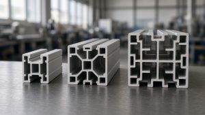 Engineering DesignSlot Dimensions Explained: 6 mm, 8 mm and 10 mm T-Slots
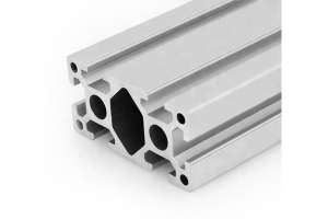 Engineering DesignWhat Is a 4080 Aluminium Profile? (Weight, Slot and Load)
 Engineering DesignModular Aluminium Components: Where the System Saves Money and Where It Costs You
 ApplicationsBuilding with T-Slot: Frames, Fences, Workbenches and Guards
 Sourcing and ProcurementDistributor Terms: Territory, Margin and Price Protection
 Sourcing and ProcurementPayment Terms for Aluminium Profile Orders (T/T, L/C and the Risk)
 Materials and EngineeringAnodised vs Powder Coated Aluminium Profiles: A Specification Guide for European Buyers
 Sourcing and ProcurementAluminium Profile Price Breaks: How Volume Changes the Unit Price
