Quick answer
Measure four things and the guessing stops
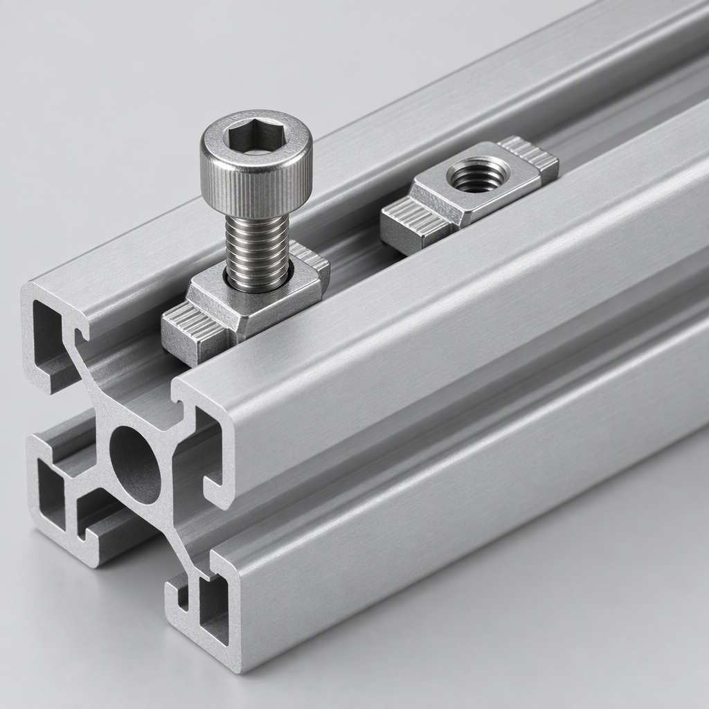
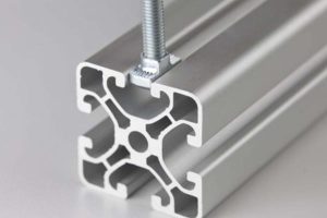
Slot mouth width — the gap between the two lips, measured across the opening. This decides which nut neck will enter, and it is the dimension everyone quotes as “6 mm”, “8 mm” or “10 mm”.
Groove cavity width — the widest part inside the slot, behind the lips. This decides whether the nut head can turn and seat. A 12 mm cavity is standard for an 8 mm mouth; a 14 mm cavity goes with a 10 mm mouth.
Cavity height — how much room the nut body has. Too little and the nut will not turn; too much and the nut sits loose and never develops preload.
Slot pitch — the distance between the centre lines of adjacent slots on a face, or between the slot and the centre bore. This is what decides whether a bracket’s bolt holes line up, and it is the dimension buyers forget entirely.
Why the name is not enough
The same series name hides different slots
“30 series” and “40 series” are shorthand for an envelope, and nothing more. Within one nominal series you will find different slot mouths, different groove cavities and different slot pitches, because the slot is sized to the wall and the wall is a choice.
The clearest example in our own range: the light-wall 30 × 30 mm section has a 6 mm slot mouth taking M5 hardware, while the standard 30 series slot takes M6 hardware in an 8 mm mouth. Both are “30 series”. Both are 30 × 30 mm on the outside. Put the M6 nut into the light-wall profile and it will not enter the mouth; put the M5 nut into the standard profile and it will turn in a cavity that is too large to hold it square.
This is not a defect — a light-wall profile physically cannot carry a large slot without losing the wall thickness that gives it strength. It is simply a fact that the series name conceals, and it is why the measurement below matters more than any catalogue table.
The rule that prevents almost every compatibility problem
Match the nut to the slot by measurement, and match the thread to the load. The slot decides the nut’s neck and head; the load decides its thread. Buy the hardware after you have measured the profile, never before — and never assume two profiles with the same series name share a slot.
The measurement
How to measure a slot properly in five minutes
Use the inside jaws of a vernier across the opening, at the narrowest point between the two lips. Take three readings along the length — 200 mm apart on a long bar — because die wear shows up as a variation in the mouth rather than in the envelope.
Open the jaws inside the slot, behind the lips, and find the widest span. You are measuring a blind feature, so read the jaws against the groove walls rather than trusting the scale alone. This is the number the nut head has to fit across.
Measure from the underside of the lip to the slot floor, using the depth rod on the vernier. Compare it with the nut body thickness. A nut that is too thick will not turn into place; too thin and it will sit at an angle and never develop preload.
Measure centre-to-centre between two adjacent slot openings on the same face, then measure from a slot centre to the centre bore. On a four-slot 40 series section this is 30 mm; on a 45 series it is 33 mm. Print it on the drawing.
Two practical notes. First, measure a cut end, not a milled surface — the extruded section is what the nut sits in, and an anodised or painted face measures differently from a bare one. Second, measure the profile you will actually assemble. If the frame will be anodised, hard anodising adds 20–40 µm per surface, which narrows the mouth by up to 80 µm across the opening. That is enough to turn a nut that slides in freely into one that needs a mallet.
mouth + 2 × anodising ≤ nut neck + 0.1 mm clearanceThe fit check for an anodised profile. Hard anodising builds on both lips, so the effective mouth narrows by twice the coating thickness.Matching
The nut-to-slot matching table
Once you have the four measurements, the nut choice follows mechanically. This table gives the slot and fastener data for our own nut range, from the smallest series to the largest, so you can match the profile you measured against it.
| Nut | Slot mouth | Groove cavity | Body length | Thread | Torque ceiling |
|---|---|---|---|---|---|
| 20 series | 6 mm | 10.0 mm wide, 4.3 mm deep | 10 mm | M5 × 0.8 | ~3 N·m |
| 30 series | 8 mm | 12.0 mm wide, 6 mm high | 12 mm, 20 mm option | M6 × 1.0 | ~6 N·m |
| 40 series | 8 mm | 12 mm wide | 15 mm, 20 mm option | M8 × 1.25 | ~15 N·m |
| 45 series | 10 mm | 14.0 mm wide, 8 mm high | 15 mm, 20 mm option | M8 × 1.25 | ~15 N·m |
| 50 and 60 series | 10 mm | 14 mm wide | 20 mm | M10 × 1.5 | ~30 N·m |
Three things this table makes obvious, and that a series name does not:
- The 30 series and the 40 series share the same 8 mm mouth. A nut for one will enter the other. What differs is the cavity height, the body length and the thread — 6 mm cavity and M6 against a deeper cavity and M8. The mouth alone tells you nothing about which one you have.
- The 45 series and the 50 series both use a 10 mm mouth and a 14 mm cavity. They are close enough to be confused and far enough apart to matter: the 45 series runs a 33 mm pitch, the 50 series a 35 mm pitch, so a bracket drilled for one will not bolt onto the other.
- Torque ceiling tracks the series, not the thread. M8 appears in both the 40 and 45 series at about 15 N·m, because the limit is the slot lip rather than the screw. M10 in the 50 series reaches about 30 N·m because both the lip and the cavity are bigger.
The mistake that costs the most
Buying hardware before the profile arrives. Nuts, brackets and joining plates are all cut to one series, and there is no shimming or adapting that turns a 33 mm pitch bracket into a 35 mm pitch bracket. Order the profile, measure it, then order the hardware against the measurements. On a repeat order, keep the measurement sheet with the drawing so the next buyer does not have to start again.
Cross-series
What happens when two series meet
Frames often need two different sections — a heavy column with lighter rails, or a light frame with a stiff rail bed. Where they meet, nothing from either series fits properly, and the joint has to be designed rather than assembled.
| Situation | What fails | The workable solution |
|---|---|---|
| 40 series bracket on a 45 series profile | The bolt holes miss the 33 mm pitch, and the M8 nut sits in a 14 mm cavity with room to move | Use a 45-series bracket. An adapter plate only helps if it is drilled for both pitches |
| 40 series profile butted to a 45 series profile | The 5 mm envelope step, and no internal connector spans both core bores | A flat joining plate across both faces, bolted into each series’ own slot. Accept the visible step |
| 30 series rail into a 40 series column | The 8 mm mouths match but the cavity heights and nut bodies do not, so one nut will not seat | Use a 40-series nut and bracket on the column side, and a 30-series bracket on the rail side, tied with a plate |
| Light wall 30 series with standard 30-series hardware | The M6 nut will not enter the 6 mm mouth of the light-wall profile | Use the M5 hardware the light-wall profile is designed for, or step up to the standard wall |
Choosing
Choosing a series in the right order
- Span and load first. Work out the unsupported span and the load it carries. That fixes the section stiffness you need and therefore the envelope and wall.
- Then the slot class. A 40 series slot in an 8 mm mouth takes an M8 nut at about 15 N·m; that is the joint capacity you get. If the joint needs more, the slot class has to change, not just the bracket.
- Then the accessories. Panels, hinges, feet and cable management all have a minimum slot. Panel mounting blocks fit 6, 8 and 10 mm slots; slot covers come in 6.2, 8.2 and 10.2 mm widths. Confirm each accessory before committing to a series.
- Then the pitch. Check every bracket and joining plate against the profile’s pitch, and write the pitch on the drawing. This is the step that is skipped and the one that stops a frame being assembled.
- Then standardise. Where the design allows it, use one series for the whole frame. One bracket, one nut, one torque figure, one spare parts box.
Our full range is grouped by series: 40 series and 45 series cover most industrial frames, with 30 series for lighter structures and the complete section range listed by size. The matching hardware is under fastening elements.
Frequently asked questions
What is the most common aluminium profile size?
40 × 40 mm is the most common framing size worldwide, with an 8 mm slot mouth and a 30 mm slot pitch. It sits at the point where the slot is large enough for a robust fastener, the section is stiff enough for the spans most machines use, and the accessory range is stocked by every supplier. 30 × 30 mm is the common light-duty size and 45 × 45 mm the common heavy one.
How do I know which size nut fits my profile?
Measure the slot mouth, the groove cavity width and the cavity height, then match them to the nut’s neck, head and body. The mouth decides whether the nut enters, the cavity width whether the head can turn, and the cavity height whether it seats squarely. Never choose a nut by series name alone, because different wall variants within one series can use different slot sizes.
Do 30 series and 40 series profiles use the same nuts?
No, even though both can have an 8 mm slot mouth. The 30-series nut is M6 with a 12 mm body in a cavity about 6 mm high; the 40-series nut is M8 with a 15 mm body in a deeper cavity. The nuts will physically enter either mouth, which is exactly what makes the mistake easy to make and expensive to find.
What is slot pitch and why does it matter?
Slot pitch is the centre-to-centre distance between adjacent slots, or between a slot and the centre bore. It is typically 30 mm on a 40 series section, 33 mm on a 45 series and 35 mm on a 50 series. Brackets and joining plates are drilled to a specific pitch, so a bracket for one series will only ever bolt through one hole per face on another. It is the dimension most often left off a drawing.
Can I use a 40 series bracket on a 45 series profile?
Not properly. The bolt holes will miss the 33 mm pitch, and the M8 nut will sit in a 14 mm cavity with enough room to move that it will not hold position. Use the correct bracket for the series. Where two series must meet, use a flat joining plate bolted into each series’ own slot, and accept the visible envelope step.
Does anodising change whether hardware fits?
Yes. Hard anodising builds 20–40 µm per surface, and a slot has two lips, so the effective mouth narrows by up to 80 µm. That is enough to change a nut that slides in freely into one that needs force, and a nut that does not seat squarely will never develop proper preload. Specify the nuts against the anodised slot, not the mill-finish slot.
Send us a section drawing or a photo of the slot
Give us the envelope and the slot measurements, or just the profile you are replacing. We will match the section and supply the nuts, brackets and plates that actually fit it.
Related reading
Twelve more engineering notes from this blog, picked for this article — plus every category below.
 Applications20 Series T-Slot Profiles: Where the Limits Actually Are
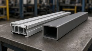 Engineering DesignAluminium vs Steel, Extruded vs Cast: What Actually Changes
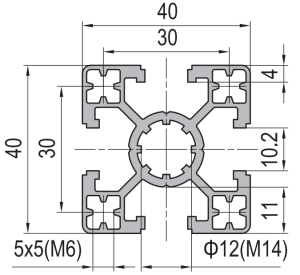 Engineering Design4040 T-Slot Aluminium Profile for Machine Frames: Choose It by Deflection
 Engineering DesignCut-to-Length, Drilling and Tapping: What Fabrication Adds
- Engineering DesignAluminium Profile Standard Sizes: How the Series Matrix Actually Works
 ApplicationsAluminium Partitions: The Three Performance Numbers Behind the Aesthetic
 ApplicationsAluminium Profiles in Industry and Construction: One Material, Two Acceptance Logics
 Engineering DesignCross-Brand T-Slot Compatibility: Interchangeability Is a Hardware Question
 ApplicationsAluminium Profile Fish Tank Frames: Glass Load, Salt Water, and the Alloy Question
 Sourcing and ProcurementDistributor Terms: Territory, Margin and Price Protection
 Quality and InspectionHow to Choose (and Audit) an Aluminium Extrusion Supplier
 Quality and InspectionSampling and First Article Approval for Aluminium Extrusion
