Cut-to-Length, Drilling and Tapping: What Fabrication Adds
Expect 12–20 days on an existing die and mill finish, or 30–40 days with a new die and anodising, before fabricated members leave the plant — then add CNC queue for holes and taps. Fabrication turns stock bars into kit parts with cut length ±0.5 mm, hole position ±0.2 mm and end square within 0.3 mm.
Short answer
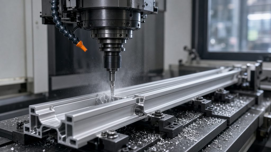
Fabrication adds cut-to-length, drilling, tapping and related CNC so profiles arrive as assembly-ready members instead of full mill bars. Lead time still starts from the extrusion path — 12–20 days on an existing die and mill finish, 30–40 days with a new die and anodising — then CNC is scheduled on those bars. Default holds are cut length ±0.5 mm, hole position ±0.2 mm and end square within 0.3 mm. Send PDF, DWG, DXF, STEP or IGES with hole and thread call-outs; a workbench kit is a cut list plus hardware, not a welded frame. Skipping drawing review before CNC is how hole patterns miss the slot grid on site.
Can you supply a workbench as a kit cut to size
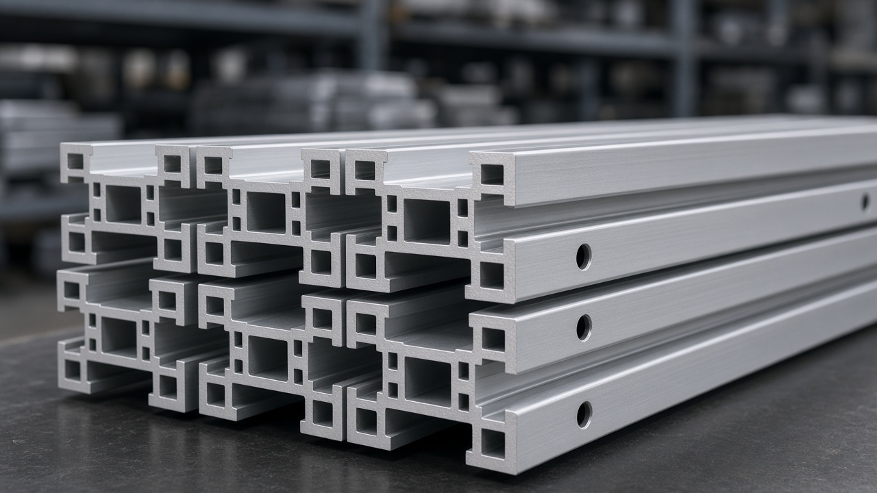
Yes — a workbench ships as a cut-to-size kit of labelled members, not as a welded assembly, when the drawing set includes a cut list, hole map and series/slot call-out.
Each rail is sawn to length, optionally drilled and tapped, deburred and packed with matching hardware if ordered. The buyer assembles on site with T-nuts and brackets, which is what automation integrators expect for cells that will be reconfigured. The table lists what a typical kit RFQ must lock.
| Kit element | What to specify | Default hold | Notes | Owner |
|---|---|---|---|---|
| Top / long rails | Series, length, qty | Length ±0.5 mm | Often 4040 or 4080 | Design |
| Legs / uprights | Series, length, foot holes | Hole ±0.2 mm | Match slot grid | Design |
| Cross members | Cut list + labels | End square 0.3 mm | Bag for assembly | Buyer |
| Holes / taps | Dia, thread, depth, datum | Position ±0.2 mm | M5–M8 common | Design |
| Finish | Mill or anodised | — | Affects calendar | Buyer |
| Hardware (optional) | T-nuts, brackets, feet | — | Match slot mouth | Buyer |
Do you offer cut to length and drilling service
Yes — cut-to-length, drilling and tapping are offered as secondary fabrication on extruded bars, quoted from the finished-part drawing.
Sawing produces the blank length; CNC drilling and tapping add mounting features in one or more clamp setups. Countersinks, slots and simple end mills are in the same family of work. Tolerances default to cut length ±0.5 mm, hole position ±0.2 mm and end square within 0.3 mm unless the drawing tightens them. Anodising can run before or after machining depending on whether machined faces must stay bare for earth continuity or fit. Formats accepted for programming are PDF, DWG, DXF, STEP and IGES.
What happens at each step
Every fabricated order passes drawing review, bar preparation, CNC, deburr/inspect and pack — in that order — so hole patterns are frozen against one revision before metal is cut.
Drawing review confirms series, slot, datums, thread call-outs and whether finish is before or after machining. Bars are extruded or pulled from an existing die run (12–20 days mill on an existing die; 30–40 days when a new die and anodising are required). CNC then saws and machines to the cut list. Deburr and first-article checks catch burr and position errors before bulk packing. Labels match the kit BOM so the integrator floor does not sort anonymous lengths. Die and metre-price questions remain upstream: how die cost amortises per meter, minimum order with a new die, die making adds 7–12 days, who owns the die.
What we need from you to start
To start we need a revision-controlled finished-part drawing, the profile identity, alloy/temper, finish sequence, quantities and a clear hole/thread map.
Acceptable files are PDF, DWG, DXF, STEP and IGES. State whether members are from a catalogue die or a new custom section. Mark datums for hole positions; “drill as needed” is not programmable. If a sample member must be approved before the kit ships, write that gate on the RFQ. With those inputs fabrication can be quoted as a line beside extrusion rather than as an afterthought change order.
RFQ checklist — fabricated profile kit
- Profile ID — catalogue code or custom section + slot.
- Cut list — length, qty, label per member.
- Hole / thread map — diameter, depth, position, datum.
- Tolerances — or accept ±0.5 / ±0.2 / 0.3 mm defaults.
- Finish sequence — mill, or anodise before/after CNC.
- Files — PDF + DWG/DXF; STEP/IGES for complex CNC.
- Sample gate — yes/no and quantity.
- Hardware — include or buyer-supply, matched to slot.
Send the cut list and the hole map together. A length-only PO forces a second CNC order after the bars land.
Four fabrication failures to avoid
Related on this site
- how die cost amortises per meter — tooling share inside the metre price
- minimum order with a new die — 150 m existing vs 500 m new
- die making adds 7–12 days — calendar before first bars
- who owns the die — tooling title after the trial
Terms used in this article
- Cut-to-length
- Sawing extruded bars to the finished member length on the drawing, with a stated length tolerance.
- Secondary fabrication
- Drilling, tapping, milling and related CNC performed after extrusion.
- Kit
- A labelled set of cut and machined members that assemble on site with T-slot hardware.
- End square
- How far the cut face departs from perpendicular to the bar axis; held within 0.3 mm by default.
- Datum
- The reference face or feature from which hole positions are measured on the drawing.
Questions buyers ask
What do you need from me to start?
A revision-controlled finished-part drawing (PDF plus DWG/DXF; STEP or IGES when CNC is complex), profile identity, alloy/temper, finish sequence, cut list and a hole/thread map with datums. With that package we can quote fabrication beside extrusion instead of as a late change.
Can I approve a sample first?
Yes. Order one fabricated member or a short first-article set, approve length and hole positions, then release the kit. Write the sample gate on the PO so bulk CNC does not run ahead of sign-off.
What happens if my drawing changes?
Issue a new revision. Hole moves on an unchanged section usually mean a CNC program update only. Section changes can require a new die and restart the 30–40 day new-tool path. Do not verbally patch coordinates into an open order.
How do I track the order?
Ask for stage status: drawing review done, bars available, CNC complete, inspection passed, packed. Keep the same drawing revision on every update so the kit on the water matches the BOM in your MRP.
Send the cut list and hole map
Attach the finished-part drawing and state series, finish sequence and whether a sample member must be approved first. We will quote cut-to-length, drilling and tapping against one revision.
Request a fabrication quoteRelated reading
Twelve more engineering notes from this blog, picked for this article — plus every category below.
 Engineering DesignT-Slot Aluminium: The Slot Mouth Is the Interface Standard, Not the Series Name
 Engineering DesignHow to Choose the Right T-Slot Aluminium Profile Size
 Quality and InspectionGood vs Bad Aluminium Profiles: What Your Receiving Dock Can and Cannot Check
 Engineering DesignWhat EN 755-9 Allows: Aluminium Extrusion Tolerances
 Engineering DesignWhat Is a 2020 Aluminium Profile? (Weight, Slot and Load)
 Engineering DesignAluminium Extrusion Price per Meter: How the Number Is Built
 Sourcing and ProcurementAuditing an Aluminium Profile Supplier: Factory, Trader, or Something in Between
 Quality and InspectionAluminium Extrusion Certificates and Standards Explained (EN 755, EN 12020, ISPM 15)
 ApplicationsCleanroom and Medical Framing: There Is No Medical-Grade Aluminium Extrusion
 Materials and EngineeringIndustrial Aluminum Profiles: Alloys, Tempers and How to Select Them
 ApplicationsAluminium Profiles in Solar Mounting: Wind Uplift, Corrosion and a 25-Year Life
 Materials and EngineeringAluminum Extrusion Tolerances: How to Write a Specification Your QC Team Can Actually Inspect
