Building with T-Slot: Frames, Fences, Workbenches and Guards
The everyday joint is an external corner bracket with M6 or M8 T-nuts: it squares a bay fast, stays serviceable, and carries bench and guard loads when torqued correctly. Build from that joint, then size the section for span and deflection — not the other way round.
Short answer
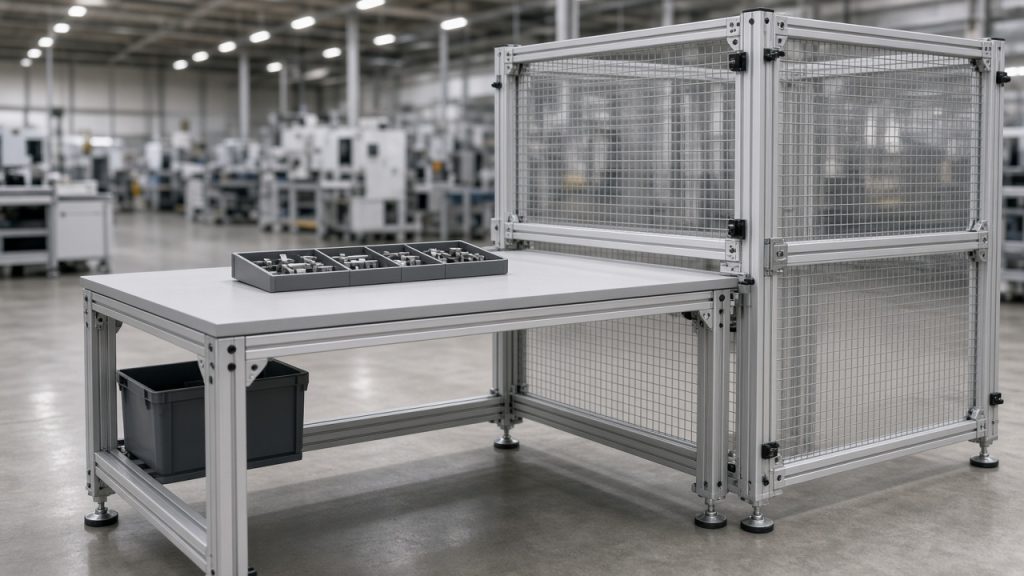
Design a T-slot frame by fixing the load path first: legs and perimeter in 3030 or 4040 for light benches, 4040 or 45 × 90 for industrial tops and long guard bays, then joints as external brackets (or end taps for high axial posts), then panels and mesh sized to ISO 13857 opening rules. Fabrication that keeps bays square: cut length ±0.5 mm, hole position ±0.2 mm, end square within 0.3 mm. Dry torque bands: M6 T-nut joints 5–8 Nm, M8 13–20 Nm. A site heavy rail example is a 45 × 90 mm six-slot in 6063-T5 at 4.10 kg/m with I ≈ 68 cm⁰ on the strong axis — useful only if the joints do not slip. The build sequence is the same for workbenches, perimeter fences and machine guards: square one bay, release the cut list, then add tops, panels and interlocks.
How do i design a workbench with t-slot extrusion
Design a T-slot workbench from the top load and bay length first, then pick the series (3030 for short light benches, 4040 or a rectangular 45 × 90 for industrial tops) so deflection stays inside your limit before you draw a single bracket.
Write a one-page design basis: overall L × W × H, top mass and live load, mid-span deflection limit (often L/500 for a “solid” feel), floor type, casters or feet, and whether shelves, vices or ESD mats are fixed. Choose one metric slot family so T-nuts, brackets and panel retainers stay interchangeable. Place the deeper axis of any rectangular rail in the primary bending direction. Keep accessory rails (tool boards, cable trays) off the primary load path. Square the first bay on paper with matching side lengths and planned diagonals; do not invent stiffness with oversized steel brackets on a light 2020 perimeter.
| Design input | Typical industrial choice | Reject if |
|---|---|---|
| Top live load | 50–150 kg mid or distributed | Unstated “heavy duty” |
| Bay length | 0.8–1.2 m between posts | >1.5 m on lone 3030 |
| Primary rail | 4040 or 45 × 90 strong axis | 2020 as sole perimeter |
| Deflection target | L/500 (2 mm at 1 m) | “Looks stiff” only |
| Joint family | External bracket + T-nuts | Blind connector as primary |
| Floor interface | M10/M12 leveling feet or locking casters | Bare ends on uneven floor |
| Finish | Clear anodise (plant) / powder (colour) | Unspecified mill for wash-down |
How do i build a workbench with t-slot extrusion
Build by cutting square, dry-fitting one bay, checking both diagonals, then torquing brackets in stages — never by forcing a crooked cut with the bolts.
Cut rails to length within ±0.5 mm and keep end square within 0.3 mm; drill any clearance or tap holes on the slot centreline within ±0.2 mm. Deburr slot mouths so T-nuts seat fully. Assemble one rectangular bay on a flat surface with joints snug but not final; measure diagonals and correct the long joint before torque. Apply dry torque in the working bands: about 5–8 Nm for M6 T-nut joints and 13–20 Nm for M8, unless the fastener maker publishes a different chart. Add lower stretchers, then the top frame, then feet or casters. Fit the worktop last so it does not hide a racked bay. For tall uprights that take axial load into a rail face, end-tap the core (M5 on light 2020, M6/M8 on 30/40 series) rather than relying on a single thin L-bracket.
| Build step | Control | Fail mode if skipped |
|---|---|---|
| Cut + square | ±0.5 mm / 0.3 mm square | Wedge gap, racked bay |
| Deburr slot mouth | Nut seats flat | False torque / lip damage |
| Dry-fit first bay | Both diagonals equal | Error copied to all bays |
| Torque in stages | M6 5–8 Nm; M8 13–20 Nm | Slip under live load |
| Feet / casters | Jam nuts locked | Walk or tip on floor slope |
| Top last | Supported on rails, not screws alone | Top used to “pull square” |
| End tap (if axial) | Core tapped to depth | Lip-only bracket as post joint |
What is the bill of materials for a workbench
A usable workbench BOM lists every cut length, connector, fastener, foot and panel as separate lines — not a single “frame kit” line that hides missing T-nuts.
Separate standard catalogue parts from any custom plate or top. Call out series and slot (for example 40-series 8 or 10 mm mouth), finish, and torque note on the assembly drawing. Count T-nuts and bolts per joint, not per frame: a four-leg bench with eight corner brackets and four gussets can need forty-plus fasteners before you add shelves. Label left/right identical cuts so the shop does not reverse mitres. For OEM SKUs freeze the BOM revision before the first dealer kit ships; a silent swap of bracket thickness changes racking stiffness.
| BOM line | Example (1.2 × 0.7 m bench) | Qty note |
|---|---|---|
| Legs | 4040 × 850 mm, anodised | 4 |
| Long rails | 4040 or 45 × 90 × 1200 mm | 4–6 (top + stretcher) |
| Cross rails | 4040 × 700 mm | 4–6 |
| Corner brackets / gussets | Matching series L or triangle | 8–16 |
| T-nuts + bolts | M8 (or M6 on 30-series) | Per hole + 10% spares |
| Leveling feet / casters | M12 feet or locking casters | 4 |
| Worktop | Plywood / phenolic / ESD laminate | 1 + underside fixings |
| Optional panel / shelf | PC / mesh / sheet + retainers | As layout |
What opening size is allowed in a machine guard fence
Allowed opening size is set by the distance to the hazard under ISO 13857 (reaching through), not by what mesh looks dense in a catalogue photo.
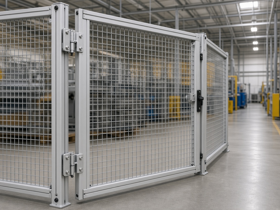
For persons 14 years and older, Table 4 of ISO 13857 links the narrowest opening dimension e to a minimum safety distance sr to the hazard. Narrow slots let a fingertip in but need only millimetres of stand-off; once the slot admits a finger or hand, sr jumps to tens or hundreds of millimetres; openings that admit an arm push sr toward 850 mm. Mesh and polycarbonate must keep their shape under load — a soft panel that spreads under push effectively enlarges e. Removable guards need interlocks where risk assessment requires them; a modular T-slot fence is not a safeguard by itself. Size the frame series to panel span (30/40-series for most perimeter bays; step up for heavy PC or long unsupported mesh), retain panels with gaskets or clamping strips matched to thickness, and anchor floor plates so the fence cannot tip into the hazard.
| Slot opening e (narrowest) | Min sr to hazard (ISO 13857) | Typical fence use |
|---|---|---|
| ≤4 mm | ≥2 mm | Fine mesh near low-risk zones |
| 4–6 mm | ≥10 mm | Dense mesh viewing panels |
| 6–8 mm | ≥20 mm | Common light mesh |
| 8–10 mm | ≥80 mm | Standard industrial mesh |
| 10–12 mm | ≥100 mm | Coarser mesh — move fence out |
| 12–20 mm | ≥120 mm | Hand can enter — check layout |
| 20–120 mm | up to ≥850 mm | Arm reach — usually wrong for close guards |
RFQ checklist — frames, benches and guards
- Application — workbench, perimeter fence, machine guard or mixed cell.
- Loads and spans — top mass, live load, bay length, deflection limit.
- Series and slot — 3030 / 4040 / 45 × 90 and mouth size for hardware.
- Joints — external brackets, gussets, end taps; which corners are structural.
- Fabrication — cut ±0.5 mm, holes ±0.2 mm, end square 0.3 mm.
- Guard openings — mesh/PC thickness and e vs hazard distance (ISO 13857).
- Interlocks — whether removable panels need safety switches.
- Heavy rail option — 45 × 90 six-slot, 6063-T5, 4.10 kg/m, I ≈ 68 cm⁰ when joints hold.
Ask one question before cutting: what is the mid-span deflection limit under the stated live load. If that number is missing, the series choice is a guess.
Four ways a build fails
Related on this site
- how die cost amortises per meter — cost of locking one series for a bench SKU
- minimum order with a new die — when a custom guard section needs tooling
- die making adds 7–12 days — calendar if you change the slot family
- who owns the die — reuse rights on a custom frame section
Terms used in this article
- T-nut
- A nut that seats in the T-slot and accepts a machine screw to clamp brackets or panels.
- Bay
- One rectangular module of a frame, defined by four members and their joints.
- End tapping
- Drilling and tapping the profile core so a butt fastener can join end-to-face under axial load.
- Safety distance (sr)
- Minimum distance from a guard opening to a hazard zone under ISO 13857.
- Opening (e)
- Narrowest dimension of a slot, square or round opening in a guard panel.
- Preload
- Clamping force from correct torque; what holds a bolted T-slot frame.
Questions buyers ask
What torque should I use?
On clean dry aluminium T-slot joints use about 5–8 Nm for M6 T-nut connections and 13–20 Nm for M8, unless the fastener maker publishes a different chart. Anodised slots need a slightly different torque for the same preload because friction changes. Recheck after the first transport or vibration cycle on mobile benches and guards.
Can I drill into the slot?
Yes for planned clearance or tap holes on the slot centreline — keep hole position within ±0.2 mm. Do not elongate the slot mouth with a drill to force an oversized nut; that destroys clamping geometry. Through-bolts and end taps are planned operations; random lip holes for “extra screws” often start cracks under load.
How do I join at 45 degrees?
Cut a true 45° mitre, dry-fit so faces meet without a gap, then bridge the joint with a mitre plate or angle bracket that lands T-nuts in both slots. A mitre alone without a plate is not a structural joint. For adjustable non-90° angles use a hinged or slotted bracket rated for the series, torqued in the same M6/M8 bands.
What panel thickness fits the slot?
Match panel thickness to the retainer or gasket band for your series — common clamping ranges are 2–4, 4–6, 6–8 and 8–10 mm. Thin sheet can sit in the groove with a retaining strip; thicker PC or composite usually needs external retainers or a cover panel on T-nuts. Measure the assembled opening before cutting the panel.
Send the frame sketch and load note
Share overall size, live load, deflection limit, and whether the job is a bench, fence or interlocked guard. We return a cut list, connector BOM and series recommendation with torque notes.
Request a build BOMRelated reading
Twelve more engineering notes from this blog, picked for this article — plus every category below.
 Engineering DesignWhat Your Extrusion Drawing Must Show (and What Costs You Money)
 Engineering DesignStandard vs Custom Aluminium Extrusion: The Break-Even Calculation
 Engineering DesignWhich Profile Size for Your Application: A Selection Guide
 ApplicationsAluminium Profile Shelving: It Buckles and Tips Before It Bends
- Engineering Design4080 vs 4545 Aluminium Profile: Which for Your Frame
 ApplicationsCleanroom and Medical Framing: There Is No Medical-Grade Aluminium Extrusion
 ApplicationsAluminium Profile Stairs and Platforms: The Geometry and Load Rules Behind Them
 Engineering DesignAluminium Profile Sizes: The Four Slot Dimensions That Decide Compatibility
 Quality and InspectionAluminium Extrusion Certificates and Standards Explained (EN 755, EN 12020, ISPM 15)
 Quality and InspectionHow to Choose (and Audit) an Aluminium Extrusion Supplier
 Materials and EngineeringAluminum Extrusion Tolerances: How to Write a Specification Your QC Team Can Actually Inspect
 Materials and EngineeringIndustrial Aluminium Extrusion: Five Advantages and the Conditions Attached to Each
