Quick answer
Rank connectors by direction of load, not by price
A connector that is excellent in one direction is often poor in another. Three sentences cover the whole decision.
Pulling apart? Use an internal anchor connector or an end fastener. It puts the force straight down the axis of the extrusion, which is the strongest direction aluminium has. It is the only family that reaches full capacity in pure tension.
Bending a corner? Use an external bracket, and widen the bolt spacing. Moment capacity is set by the couple arm, so a 60 mm bolt pitch beats a 40 mm pitch by 50% with no change in material.
Needs to be invisible? Use a blind connector, and accept that you have given up roughly two-thirds of the joint’s capacity to get the look.
Capacity
Relative load capacity of the six connector families
These figures are relative, not absolute, and they compare the same joint on the same 40-series profile with the same M8 fastener. Treat the end fastener as the reference at 100% and read the rest as a proportion of it. The pattern holds across series; only the absolute kilonewtons change.
Read this before you compare quotes
Suppliers quote connector capacities in whichever direction flatters the part. A “3 kN” bracket may be 3 kN in compression against the slot and under 1 kN in pull-out. Ask for the direction, the fastener used, and whether the figure is for the connector alone or for the assembled joint at a stated torque.
Load paths
Why the same joint behaves differently in three directions
Take a single 90° joint between a leg and a rail, made three different ways. Change only the direction of the load and the ranking of the three connectors inverts completely.
| Load direction | Best choice | Why | Worst choice |
|---|---|---|---|
| Axial pull-out (rail pulled away from leg) | Anchor connector | Force runs down the extrusion axis into the tapped end. Aluminium is strongest here and the slot flange is not involved | Blind connector — the expanding element has the smallest bearing area |
| Vertical shear (rail pushed down along the leg) | External bracket + T-nut | The nut bears on the slot flange over a long area, which is exactly what the extrusion profile is designed to resist | Anchor connector — a single bolt in shear with no backup |
| Rotation about the corner (moment) | External bracket, wide pitch | Capacity equals nut pull-out times the couple arm. Widening the arm is free capacity | Anchor connector — the arm is effectively zero, so the joint pivots |
| Torsion along the rail | Joining plate spanning the joint | Four bolts spread over a plate resist twist far better than two bolts in line | Any single-point connector |
This is why “which connector is strongest” is the wrong question and why the answer to “corner bracket or anchor connector” is so often both. The bracket gives you the couple arm; the anchor gives you the axial path. Used together on the same joint, they cover each other’s weakness, and the joint starts to behave close to rigid instead of close to pinned.
The hidden cost
What each connector demands before it can be installed
Connector price is the smallest part of the cost. The machining and access requirements are what decide whether a joint is buildable on a bench or needs a machining centre, and this is where most first-time frame builders get caught out.
| Connector | Profile preparation | Access needed | Assembly time per joint |
|---|---|---|---|
| External bracket | None. Cut square to length | External, from the open side | 1–2 min with a power driver |
| Anchor connector | Drill and tap the profile end, typically M8 × 25 deep; end face square to ±0.2 mm | A hole in the mating profile for the bolt, plus driver clearance | 3–5 min, plus machining |
| Blind connector | Machined bore in the profile end to a close tolerance; access hole in the mating member | None after insertion | 2–4 min, but the machining is the expensive step |
| Joining plate | None | External, both sides of the joint | 3–5 min, four nuts to seat |
| Butt connector | Both profile ends cut square and to matching length | Access to both slot faces to tighten | 2–3 min, plus alignment check |
| Pivot connector | None, or a drilled pivot hole | External | 2 min, plus a swing test |
The decision rule that saves the most money
If a joint is accessible and the frame is not panel-clad, an external bracket is almost always the right answer — no machining, adjustable, and cheap to rework. Reserve anchor and blind connectors for the joints where a bracket physically cannot go: behind a flush-mounted panel, inside a closed profile run, or where the outer face must stay clean.
Worked selections
Two frames, joint by joint
Abstract selection advice is easy to write and hard to use. Here is the same decision applied to two frames that most fabricators actually build.
Assembly
Four mistakes that make a correct connector perform badly
Under-torquing “to be safe”
A finger-tight joint is not a gentle joint. Without preload the connection creeps, the frame loses square within weeks, and every fastener downstream loosens in turn. M8 into a 40-series nut: 10–15 N·m, ceiling about 15 N·m. Use a torque wrench on the first frame, then teach the number.
Mixing series on one joint
A 45-series bracket on a 40-series profile looks almost right and holds position almost correctly. The bolt sits off-centre in the slot, the nut carries on one edge, and capacity drops by more than half. Check the slot mouth, not the outer size.
Using one bolt where the joint needs two
A single fastener in a joint is a pin. It locates but does not brace, so the structure racks. Any joint expected to hold an angle needs at least two connection points, whether that is two bolts on a bracket or a bracket plus an anchor.
Ignoring the anodised slot
Hard anodising adds 20–40 µm per surface, which narrows the slot mouth. Standard nuts then fit too tightly or need driving in, and the nut may not seat squarely. Specify nuts for the anodised slot when the frame is anodised.
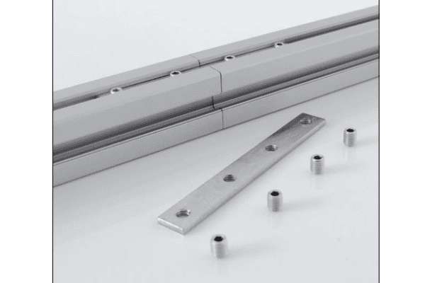
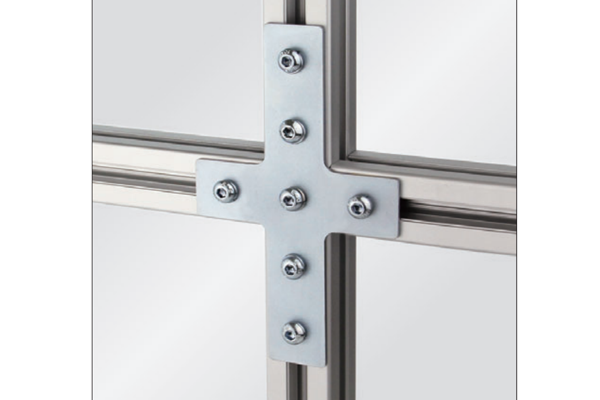
For the fasteners themselves, the matched parts are the 40 series T-nut for slot-mounted connections and the PG40 4040 joining plate for splices and bracing. Connectors are grouped under joining plates and fastening elements, and the profiles they fit are on the 40 series page.
Frequently asked questions
What are T-slot aluminum profile connectors used for?
They join aluminium extrusions without welding, using the slot along the profile to carry the fastener. That keeps the frame modular: it can be assembled with hand tools, adjusted on site, and taken apart for relocation. The connector’s job is to hold position and transfer load into the profile; the nut and bolt carry the force.
Which connector type is the strongest?
It depends on the direction of the load. An internal anchor connector is strongest in axial pull-out, because the force runs down the axis of the extrusion into a tapped end. An external bracket is strongest in shear and in resisting rotation, because the slot flange and the couple arm both work in its favour. A blind connector is weakest overall — roughly a third of an end fastener — which is the price of hiding the hardware.
Are T-slot connectors better than welding?
For modular structures, usually yes. A welded frame is permanent and cannot be adjusted or relocated without cutting. A mechanical T-slot frame can be loosened, squared and rebuilt, and it needs no welding equipment or post-weld straightening. Welding still wins where the joint must be fully rigid and never touched again, and where the material is steel rather than aluminium.
Do I need special fasteners for each connector?
Yes, and the fastener is usually what limits the joint. A bracket needs a T-nut or drop-in nut sized to the slot mouth, an anchor connector needs a tapped hole in the profile end, and a blind connector needs a machined bore. Specifying the connector without the matching nut, bolt grade and torque leaves the joint’s real capacity undefined.
Can I mix connector types on the same frame?
Not only can you, you usually should. Use external brackets on the joints nobody sees and that may need adjusting, anchor connectors where a panel has to sit flush, and heavier base brackets where the moment is largest. The one rule is consistency: keep the same connector and fastener on every joint of the same type, so a re-tighten pass uses one torque figure and one wrench.
What torque should I use on a T-slot connector?
About 3 N·m for M5 into a 20-series nut, about 6 N·m for M6 into 30 series, 10–15 N·m for M8 into 40 series, and 20–30 N·m for M10 into 50 or 60 series. In every case the ceiling is set by the aluminium slot lip, not by the steel bolt. The lower figure is what stops the joint creeping under vibration; the ceiling is where the lip or the nut thread starts to deform.
Connectors, nuts and profiles from one specification
Tell us the frame and which faces must stay clean. We will come back with the connector mix, the machining required and the fastener list as one package.
Related reading
Twelve more engineering notes from this blog, picked for this article — plus every category below.
 Materials and Engineering6063-T5 Aluminium Profile: What the Designation Actually Guarantees
 Engineering Design6063 vs 6061 vs 6082 and T5 vs T6: What Changes in Practice
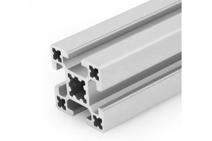 Engineering DesignWhat Is a 4040 Aluminium Profile? (Weight, Slot and Load)
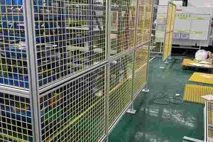 Engineering DesignRobot Cell Framing in Aluminium: Stiffness, Damping and the 2025 Safety Revision
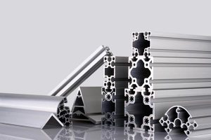 Materials and EngineeringAnodised vs Powder Coated Aluminium Profiles: A Specification Guide for European Buyers
 Engineering DesignCustom Aluminium Extrusion: From Drawing to Production
 Engineering Design2020 vs 3030 Aluminium Profile: Which for Your Frame
 ApplicationsBuilding with T-Slot: Frames, Fences, Workbenches and Guards
 Quality and InspectionAluminium Extrusion Certificates and Standards Explained (EN 755, EN 12020, ISPM 15)
 Sourcing and ProcurementPayment Terms for Aluminium Profile Orders (T/T, L/C and the Risk)
 ApplicationsESD-Safe Aluminum Profile Workbenches: Why Anodising Alone Fails the Audit
 Machine SafetyAluminium Profile Machine Guards: Size the Frame from the Energy, Not from the Mesh
