Robot Cell Framing in Aluminium: Stiffness, Damping and the 2025 Safety Revision
A robot cell is usually specified as a frame with a robot bolted to it. It is actually a stiffness and damping problem, a fatigue problem, and now a standards problem, because the robot safety standards were revised in 2025 and the EU machinery rules change in 2027.
Short answer
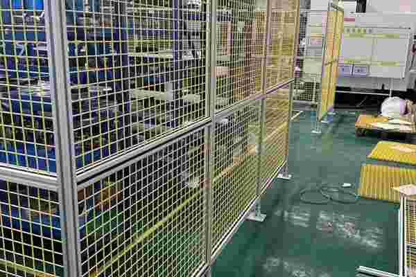
An aluminium T-slot frame is the default structure for a robot cell because it is modular, it can be reworked as the process changes, and it is stiff enough when it is sized by stiffness rather than by stress. The three things that decide whether the cell performs are the stiffness of the frame and the base plate, the damping of the whole assembly, and the fatigue behaviour of the joints. Aluminium has no fatigue limit, so a frame that sees a robot accelerating millions of times is a fatigue design even though the stresses are low. On top of that, the governing safety documents moved in 2025: ISO 10218-1 and ISO 10218-2 were published in their new editions, and in the EU the Machinery Regulation (EU) 2023/1230 applies from 20 January 2027, replacing the Machinery Directive. Two practical traps follow: a T-slot frame is not a safety guard, and an anodised frame does not conduct electricity, so it cannot be used as an equipotential bonding path without being dealt with deliberately.
A robot cell is a stiffness and damping problem before it is a strength problem
The loads a robot puts into its frame are modest. A mid-size industrial arm might apply a few hundred newtons at the tool, and the reactions at the base are well within the capacity of a 45 or 60 series profile. What a robot does apply is motion, and motion is where a lightweight frame behaves differently from a welded steel bench.
Two parameters matter. The first is static stiffness: how far the tool deflects under a given force. Static stiffness sets the accuracy of the cell under a steady load, and it is dominated by the base plate and the first metre of structure, because deflection accumulates from the floor upwards. The second is dynamic behaviour: the frame has natural frequencies, and if the robot excites one of them the tool vibrates. Vibration shows up as a positioning error, as a longer settling time, and therefore as a longer cycle.
Aluminium is stiff, but it is not as stiff as steel for the same section: the elastic modulus is around 70 GPa against about 210 GPa. What aluminium has is a much better stiffness per kilogram, so for a given mass budget a well-designed aluminium section can be deeper and therefore stiffer than a steel one. The design consequence is that a robot cell frame should be sized by a deflection limit at the tool, not by a stress check, and that depth and the base plate do most of the work.
| What decides the cell | Why it decides it | What to specify |
|---|---|---|
| Static stiffness at the tool | Deflection accumulates from the floor up, so the base dominates | A deflection limit at the tool, and a stiff base plate, not a stiff beam alone |
| Dynamic behaviour | A natural frequency inside the robot’s motion band shows up as settling time | Mass, damping and joint rigidity; avoid slender cantilevers |
| Joint fatigue | Aluminium has no fatigue limit, so cycles accumulate damage | Preloaded joints, generous radii, no point loads on slot lips |
| Safety function | The frame often carries the guard, the interlock and the fence | Treat safety-related parts as safety-related, and document them |
| Electrical continuity | An anodised frame is insulated, so it cannot be a bonding path by default | A bonding plan with dedicated conductors and tested continuity |
Aluminium has no fatigue limit, and a robot loads its frame millions of times
Steel has a fatigue limit: below a certain stress range, a steel detail can be cycled indefinitely and the S-N curve flattens out. Aluminium does not. Its S-N curve keeps falling, so there is no stress range below which a cycle is free. Every cycle of a robot move takes a little life out of the detail that carries it.
In practice this does not mean aluminium is unsuitable; it means the design has to be done on stress range rather than on peak stress, and it means the details matter more than the section. A fatigue crack starts where stress concentrates: at a sharp change of section, at the toe of a weld, at the root of a thread, and at a slot lip that is being point-loaded. A bolted joint that is properly preloaded does not fret and does not fatigue at the bolt hole, because the clamp force carries the load as friction. A joint that is loose rocks, frets, and initiates a crack.
The controls are ordinary. Use brackets that spread load into the profile instead of loading a slot lip. Keep the number of joints in the load path small. Preload fasteners to the manufacturer’s torque for the actual friction condition. And where a robot applies a genuinely cyclic load to a cantilever, check the stress range rather than the static stress, because the static check will pass.
The safety standard changed in 2025: ISO 10218-1 and ISO 10218-2
ISO 10218-1 and ISO 10218-2 were published in new editions in 2025, the first major revision of the industrial robot safety standards in well over a decade. Part 1 addresses the robot itself and Part 2 addresses the robot system and its integration, which is the document a cell builder works to.
The significance for a frame supplier is that the boundary between the robot and its installation has become more explicit. Functional safety requirements, the treatment of collaborative applications, and the expectation that the integrator performs and documents a risk assessment all sit in Part 2. A frame that is described as a structure and a fence that is described as guarding are no longer separate conversations: the assembly has to be assessed as a system, and the safety-related parts of the control system have to be designed to a performance level.
For a buyer, this changes what should be in the enquiry. Instead of asking for a frame with guarding, the enquiry should say which safety functions the structure carries, what the required performance level is, and who is producing the risk assessment. A profile supplier can provide the structure and the guard frame; it cannot certify a safety function.
The EU machinery rules change in 2027 as well
In the European Union, Regulation (EU) 2023/1230 replaces the Machinery Directive 2006/42/EC and applies from 20 January 2027. It is a regulation rather than a directive, so it applies directly without national transposition, and it modernises the framework for digital instructions, software, and machinery that includes artificial intelligence or autonomous functions.
For a robot cell built on an aluminium frame, the practical effects are documentation and traceability. Technical documentation, the declaration of conformity, and the instructions have to be maintained for the life of the machine and produced in a digital form where required. If the frame carries a safety function, that function is part of the machinery and is inside the assessment. A cell that is assembled on site from a kit is still a machine, and the person who places it on the market is the manufacturer for the purposes of the regulation.
None of this changes the profile. It changes the paperwork that has to accompany the assembly, and it is worth knowing before a cell is designed, because a safety function that is discovered late is expensive to add.
A T-slot frame is a good structure and a poor safety fence
This is the most common confusion in a robot cell specification. A T-slot frame is an excellent structure and an excellent carrier for panels. It is not, by itself, a guard.
A guard has to contain a hazard, and that means it has to have a defined impact resistance, a defined opening size that keeps a person out, and a defined fixing that will not pull out. A slotted aluminium post with a thin panel in it may satisfy none of those, and a slot that accepts an M8 bolt is also an opening. The guard design has to follow the machine guard standard for the hazard, with the panel thickness and the fixing chosen for the impact, and the frame then sized to carry that panel.
There is also a serviceability point. A guard that is bolted into a slot can be removed in a minute by anyone with an Allen key, which is convenient during commissioning and dangerous during production. Where a guard is a safety-related part, its fixing should be tamper-resistant or interlocked, and the drawing should say so. The same frame can be both, but only if the intention is written down.
Anodising and the electrical problem
An anodised aluminium profile has an oxide layer that is an electrical insulator. That is an advantage for corrosion and a problem for anything that needs continuity: equipotential bonding, ESD control, and any sensor or cable tray that relies on the frame as a return path.
So a robot cell frame that is bonded has to be bonded deliberately. Bonding washers that bite through the anodic layer, dedicated conductors from part to part, and a measured continuity check at each joint, are the normal controls. The mistake is to assume that because the frame is metal it is continuous; the anodic layer is on every face that was anodised, and the joints are the places where continuity is least reliable.
The same point applies to a painted or powder-coated frame, and to a frame that mixes anodised and mill-finish parts. The bonding plan has to be a drawing, not an assumption, and it has to be verified after assembly, because continuity that is lost when a joint is re-tightened is continuity that will be lost in service.
Thermal drift and the long rail
A robot cell is often built in a workshop that is warm in summer and cold in winter, and a robot cell is a metrology problem. Aluminium expands by roughly 23 micrometres per metre per kelvin, so a six-metre rail that sees a 15 kelvin swing moves by about two millimetres. On a cell that is positioning to a tenth of a millimetre, that is a real error, and it is invisible in a static drawing.
Three controls are available. The first is to anchor the rail at one point and allow the rest to slide, so the rail grows away from the datum rather than fighting its fixings. The second is to keep the rail in a controlled-temperature enclosure, or to compensate in the control system. The third is to accept the drift and design the tolerance budget to include it. What does not work is to bolt both ends of a long rail rigidly to a stiff floor and expect the rail to stay straight: the movement goes somewhere, and it usually goes into the fixings or into a bow.
The same calculation applies to the base plate and to the mounting of the robot itself. A robot mounted on a plate that is restrained at both ends is a robot mounted on a plate that is being bowed by its own expansion.
What to send with a robot cell enquiry
The information that makes a robot cell quotation useful is not the profile list. It is the robot, the payload, the reach and the accuracy the process needs; the deflection limit at the tool; whether the cell is a fixed or a mobile platform; which safety functions the structure carries and to what standard; the electrical continuity requirement; and the temperature range the cell will see. Given those, the section and the base plate follow.
It also helps to say who is the integrator. The frame supplier builds the structure, the integrator owns the risk assessment and the safety functions, and the boundary between the two is the single most useful thing to write down before the order.
RFQ checklist — robot cell framing
- Robot and payload — model, mass, reach and the reaction at the base under the fastest move.
- Accuracy requirement — the deflection limit at the tool, stated in millimetres, and the settling time target.
- Base condition — floor type, levelness, and whether the cell is fixed or mobile.
- Safety functions — which functions the structure carries, the required performance level, and who owns the risk assessment.
- Guard requirement — impact resistance and opening size, so the panel and its fixing are specified, not assumed.
- Electrical continuity — bonding, ESD or sensor return; and whether the frame is anodised.
- Temperature range — the working range, and whether a long rail needs a sliding end.
- Reconfiguration plan — how often the cell will be reworked, which sets how much adjustability is worth paying for.
- Documentation — the standards the cell must be documented to, and the digital format required.
Ask one question before quoting: which safety functions the frame carries. It decides whether the frame is a structure or a safety-related assembly, and the two are designed and documented differently.
Four ways a robot cell frame goes wrong
Related on this site
- Machine guards to ISO 14120: impact, openings and fixings— what a guard has to do that a frame does not
- Aluminium profile machine guards under impact— sizing a guard frame for a defined impact
- ESD grounding: the four joints that break continuity— why an anodised frame is not automatically bonded
- 40 series profiles category— the range normally used for robot cell bases and fences
Terms used in this article
- Fatigue limit
- The stress range below which a material can be cycled indefinitely without accumulating damage; steel has one and aluminium does not.
- Damping
- The ability of a structure to dissipate vibration energy; a lightly damped frame rings after each robot move.
- Performance level
- The reliability a safety-related control function must achieve, expressed as a level in the machinery safety standards.
- Equipotential bonding
- Connecting conductive parts together so that they sit at the same potential, which prevents a difference driving a current through a person or a signal.
- Anodic layer
- The protective oxide film grown on aluminium by anodising, which is electrically insulating as well as corrosion resistant.
- Stress range
- The difference between the maximum and minimum stress in a cycle, which is what drives fatigue rather than the peak value.
Questions buyers ask
Is an aluminium frame rigid enough for a robot cell?
Yes, if it is sized by stiffness rather than stress, and if the base plate is treated as part of the structure. Aluminium is about a third as stiff as steel for the same section, but it is a third of the density, so a deeper aluminium section on a given mass budget can be stiffer than the steel alternative.
Which standard applies to my robot cell?
ISO 10218-2 covers the robot system and its integration, and it was published in a new edition in 2025 together with Part 1. In the EU, Regulation (EU) 2023/1230 applies from 20 January 2027 and replaces the Machinery Directive. The integrator owns the risk assessment; the frame supplier provides the structure.
Can I bond the robot to the aluminium frame?
Not by default. An anodised frame is insulated by its oxide layer, so bonding requires dedicated conductors or biting washers at every joint, plus a continuity check after assembly. Treat the bonding plan as a drawing and verify it, because continuity is easily lost when a joint is re-tightened.
Why does my cell lose accuracy through the day?
Thermal drift. Aluminium expands by roughly 23 micrometres per metre per kelvin, so a long rail moves by millimetres over a working day. Anchor the rail at one point and let it slide, control the temperature, or budget the drift into the tolerance.
Do I need a different profile for a collaborative robot?
The profile does not change; the assessment does. A collaborative application depends on the robot’s safety functions and the risk assessment, and the structure has to support whatever guarding or sensing that assessment requires. Start from the assessment, then size the frame.
Send the robot and the accuracy target
Tell us the robot, the payload, the deflection limit at the tool and which safety functions the frame carries, and we will size the base plate and the frame as one structure.
Request a quoteRelated reading
Twelve more engineering notes from this blog, picked for this article — plus every category below.
 Engineering DesignPrecision Cutting and Tapping of Aluminium Profiles: The Tolerance That Actually Matters
 ApplicationsAluminium Greenhouse Profiles: A Snow Load Problem With a Condensation Problem
 Engineering DesignAluminium Extrusion Die Cost (2026): Price by Section Size
 Engineering DesignHow to Choose an Aluminium Extrusion Profile: The Three Decisions That Bind
 Engineering DesignAluminium Profile Basics: What the Series Numbers and Slot Codes Mean
 ApplicationsHow to Choose the Right 4040 T-Slot Aluminium Profile for Industrial Applications
 ApplicationsAluminium Pergola Profiles: A Beam Problem With a Water Problem
 Engineering DesignWhat Is a 3030 Aluminium Profile? (Weight, Slot and Load)
 Materials and EngineeringAnodised vs Powder Coated Aluminium Profiles: A Specification Guide for European Buyers
 Materials and EngineeringAluminum Extrusion Tolerances: How to Write a Specification Your QC Team Can Actually Inspect
 Materials and EngineeringAluminium Extrusion Section Design: What Each Feature on the Drawing Costs You
 Quality and InspectionAluminium Profile Finishes: Choose by Failure Mode, Not by Process Name
