ESD workbenches · grounding continuity
ESD Anti-Static Workbench Grounding: The Four Joints That Break the Path
Almost every ESD bench that fails an audit fails in the same way. The worksurface reads a comfortable 107 ohms, the wrist strap passes, the footwear passes — and the overhead light arm, the pegboard and the tool rail are sitting on an insulated island. Here is where the ground path actually breaks on an aluminium profile bench, the resistance limits it has to meet, and the four-node test that finds the break in fifteen minutes.
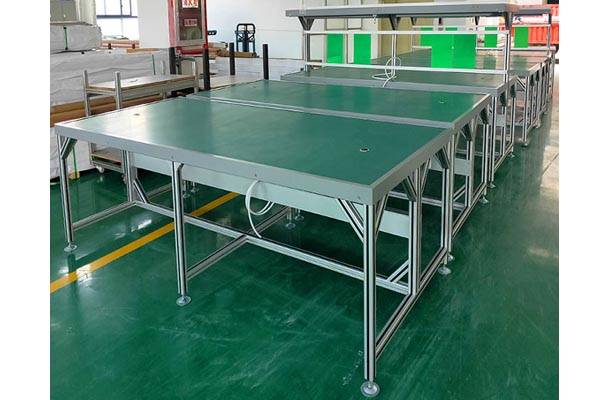
Quick answer
- The mat is tested and the frame is assumed. An ESD audit covers the worksurface, the wrist strap and the footwear. The structure underneath them is not in the test plan, which is why a bench can report a perfect surface reading while its overhead rail is floating.
- The limits are specific. Under DIN EN 61340-5-1 and ANSI/ESD S20.20 the worksurface must measure between 1 × 10⁶ and 1 × 10⁹ ohms to ground, and below 1 × 10⁹ ohms point to point across the mat.
- Four joints break the path on a profile bench: a coated corner bracket, the anodised slot face under a T-nut, the pad on a levelling foot, and any accessory added after delivery — a monitor arm, a light rail, a drawer unit.
- An anodised surface is not a conductor. The anodic film is 10 to 25 µm of aluminium oxide; a powder coat is 60 to 100 µm of polymer. Neither conducts at the 10 volts a continuity meter applies.
- Bare metal on bare metal is the only reliable path, held together by clamp load. A 40 series T-nut at its 15 N·m maximum clamps hard enough to stay conductive; the same nut at 5 N·m can read open.
- Test in the room, in its real humidity. A mat that reads 5 × 10⁷ ohms at 48 per cent relative humidity can climb past the 1 × 10⁹ ohm limit at 20 per cent.
Also searched as esd anti static workbench, anti static assembly bench, esd workbench grounding, esd workstation aluminium frame, dissipative workbench, esd bench continuity test, 40x40 aluminium profile esd bench.
Why the mat passes and the bench fails
Walk onto any electronics assembly floor and ask for the ESD audit sheet. It will list the worksurfaces with their readings, the wrist straps, the heel grounders, the ionisers and the flooring. It will almost never list the bench structure. The frame is treated as furniture, and furniture is not dissipative, so nobody measures it.
That is a defensible position right up to the moment a board fails at functional test and the failure is traced to a charged tool. A screwdriver lying on a tool rail that has no path to earth will hold whatever charge it acquired, and it will deliver it to the first board it touches. The bench still passes its audit, because the audit never asked the rail a question.
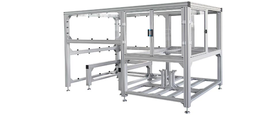
The other half of the problem is mechanical rather than electrical. An aluminium profile bench is a set of separate parts bolted together, and the parts are supplied in finishes that are chosen for appearance and corrosion resistance — not for conductivity. Every one of those finishes is a deliberate insulator. The frame looks like a continuous conductor because it is made of aluminium, and it is not one, because every interface between two members has a film of something in it.
What the standards actually require
Two documents govern most electronics assembly floors: DIN EN 61340-5-1 in Europe and ANSI/ESD S20.20 in North America. They agree on the numbers that matter here, and the numbers are what turn a vague argument about “grounding” into a test you can run and pass.
| What is measured | Limit | Test method | Who usually checks it |
|---|---|---|---|
| Worksurface to ground | 1 × 10⁶ – 1 × 10⁹ Ω | IEC 61340-4-1, 2.3 kg probe | ESD coordinator, monthly |
| Worksurface, point to point | < 1 × 10⁹ Ω | Same probe, 250 mm apart | ESD coordinator, monthly |
| Wrist strap to ground | 1 × 10⁶ – 1 × 10⁷ Ω typical | ANSI/ESD STM 9.1, worn on a hand | Operator, daily |
| Ground cord series resistor | 1 MΩ ± 10 % | Measured across the cord | ESD coordinator, quarterly |
| Bench frame and metal furniture | Bonded — defined and recorded | Continuity, 4 nodes | Almost nobody |
| Conductive containers and bins | < 1 × 10⁴ Ω | Per container family | Goods-in, by batch |
| Test voltage | 100 V above 1 MΩ, 10 V below | Set on the meter | Whoever holds the meter |
Two lines in that table are worth more attention than they usually get. The first is the ground cord resistor. It is not a tolerance, it is a safety device: with the wearer standing on a dissipative floor and wearing a wrist strap, the 1 MΩ resistor is what limits the current if the person touches a live conductor. A strap without it is a hazard, not a protection. The second is the frame line, which is where the whole argument of this article sits — the standard requires the frame to be bonded, and it requires the bonding to be defined and recorded, and on a painted or anodised frame that does not happen by itself.
The band, and why both ends matter
1 MΩ ≤ R(worksurface to ground) ≤ 1 GΩThe lower limit is operator safety. The upper limit is charge decay: above 1 GΩ a worksurface cannot drain a triboelectric charge inside a normal handling cycle, so the charge is still there when the operator picks the next board up. A reading outside the band is a failure in either direction, which is why “lower is better” is not the right instinct.
The four joints that break the path
On an aluminium profile bench there are exactly four places where continuity is lost in practice. They appear in this order of frequency.
The coated corner bracket
Die-cast or extruded brackets are commonly supplied black powder coated because it looks better than mill finish. A 60 to 100 µm polymer film sits between the bracket and both profiles, so the corner is mechanically rigid and electrically open. Everything bolted above that corner is now floating.
The anodised slot face
The T-nut head bears on the two slot lips, and on an anodised profile those lips carry the same 10 to 25 µm oxide film as the outside. The nut is tight, the joint is strong, and the contact resistance is whatever the oxide decides. This is the joint that makes a frame read open at one corner and fine at the other three.
The levelling foot pad
A nylon or rubber foot pad isolates the frame from the floor. That is usually harmless, because the floor is not the reference — the building earth is. It becomes a fault when the floor is the reference, in a programme that grounds through a dissipative floor, and the frame is expected to drain through its feet.
Everything added later
A monitor arm, a light rail, a pegboard, a drawer cabinet, a hinged guard door. Each arrives as a powder coated assembly bolted onto the frame with a coated bracket. Every one of them is a new isolated island, and the bench that was continuous at commissioning is not continuous a year later.
| Break point | What it reads | Symptom on the floor | Fix |
|---|---|---|---|
| Coated corner bracket | Open to > 1011 Ω | Frame reads open at one corner, fine at the other three | Swap to mill-finish bracket, or add a 6 mm² jumper across the corner |
| Anodised slot face | 108 – 1011 Ω | Readings drift between audits; one joint goes open after re-torque | Serrated washer under the nut head, or a masked bare land at the bonding point |
| Foot pad | > 1012 Ω | Bench passes on a hard floor, fails after a floor change | Bond the frame to earth by a separate conductor, not through the feet |
| Late accessory | Open | A tool rail or a drawer unit is live with static; nothing else changed | One jumper per disconnectable module, and a bonding stud on every accessory |
Why an anodised profile cannot be the conductor
This is the part that surprises people, because aluminium is an excellent conductor and anodised aluminium is aluminium with a surface treatment. The surface treatment is the problem. Anodising is not a coating that sits on the metal; it is an electrochemically grown oxide layer that is chemically bonded to it, and aluminium oxide is a dielectric. Anodic films are used commercially as insulating layers precisely because they hold off voltage.
The arithmetic that matters is simpler than the physics. The oxide is 10 to 25 µm thick on a standard anodised profile. The continuity meter applies 10 volts, or 100 volts if the material is already known to be above 1 MΩ. The film does not break down at either. Powder coat is three to four times thicker again and is a polymer, with a volume resistivity in the 1014 to 1016 Ω·cm range. Neither surface is a conductor at the voltages that matter here, and no amount of tightening changes that.
The counter-intuitive part
The metal itself contributes nothing measurable to the problem. A 2 m length of 40 × 40 profile has a cross-section of roughly 300 mm² and a resistance of about 0.2 milliohms. The entire resistance of a failed frame lives in the interfaces, not in the material. That is why the fix is never “a bigger profile” and always “a better joint”.
What this means for a specification is straightforward. If the frame has to be a conductor, the faces that carry the current have to be left as mill finish, and the finishing specification has to say so. Anodising the outside of a post and leaving the slot faces bare is a normal, cheap request at the extrusion stage. Trying to recover conductivity afterwards means masking and re-machining, which costs more than the anodising did.
What a conductive joint actually looks like
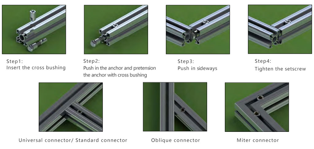
There are only three reliable ways to make a bolted profile joint carry current, and all three work on the same principle: get bare metal into contact, and hold it there with clamp load.
Mill finish at the interface
Both mating faces left un-anodised, or a small masked land at the bonding point. This is the cheapest option if it is specified before extrusion, and the most expensive if it is discovered afterwards.
A serrated washer
An external tooth or star washer under the nut head bites through the 10 to 25 µm anodic film. It works on anodising. It does not work on a 100 µm powder coat — the teeth do not reach metal, and the joint reads open while looking correct.
A bonding jumper
6 mm² green/yellow, ring terminal crimped at both ends, bolted to a masked bare spot on each side of the joint. This is the only option that also survives disassembly, and the only one that works across a painted bracket.
Clamp load is the part that gets ignored. Contact resistance between two aluminium surfaces falls as the contact pressure rises, and a T-nut joint has a small contact area — the nut head bears on two slot lips, which is a pair of narrow strips rather than a face. That is why torque is not just a structural number here, it is an electrical one.
| Fastener | Series | Torque ceiling | Pull-out, per fastener | Consequence for continuity |
|---|---|---|---|---|
| M5 T-nut, 20 series | 6 mm slot | approx. 3 N·m | not published | Small contact area; verify every joint on a 20 series ESD frame |
| M6 T-nut, 30 series | 8 mm slot | approx. 6 N·m | 600 – 900 N | Below about 4 N·m the joint can read open |
| M8 T-nut, 40 series | 8 mm slot | approx. 15 N·m | 1.5 – 2.2 kN | The workhorse of an ESD bench frame; clamp load is reliable at full torque |
| M8 T-nut, 45 series | 10 mm slot | approx. 20 N·m | not published | Larger head, larger contact patch, more tolerance of under-torque |
| M10 T-nut, 50 and 60 series | 10 mm slot | approx. 30 N·m | not published | Used where the bench also carries a machine frame |
The failure that looks like a pass
A joint tightened to a third of its specified torque feels solid, looks correct, and can measure in the 109 to 1011 ohm range rather than open. It will pass a casual check with a cheap meter and fail a proper one. If the frame is part of the ESD programme, spot-check torque with a wrench on every second nut, and treat the two checks as one procedure.
Humidity, and the reading that changes overnight
Surface resistance on a dissipative material is not a constant. It is a function of relative humidity, and it rises steeply as the air dries out. A worksurface that reads 5 × 10⁷ ohms at 24 °C and 48 per cent relative humidity sits comfortably in the middle of the acceptable band. The same worksurface in the same room at 20 per cent relative humidity can read above the 1 × 10⁹ ohm ceiling, because the adsorbed water film that carries most of the surface current has gone.
Two practical consequences follow. First, every reading has to be recorded with the temperature and the humidity next to it, or it is not a measurement, it is a number. Second, a bench that is specified and tested in summer can fail in a heated, dry winter assembly area without anything having changed. If the room runs below about 30 per cent relative humidity for part of the year, either the mat specification needs a tighter upper limit or the room needs humidification.
Record it like this
R = 5.1 × 10⁷ Ω @ 24.5 °C / 48 % RHA reading without the condition is not repeatable, and a non-repeatable reading cannot be used to decide whether a bench is in or out. This is also why an audit that reports a single number per bench is worth less than one that reports a number, a date and a condition.
The four-node continuity test
This is the test that finds the coated bracket. It takes about fifteen minutes for a single bench and it needs a resistance meter with a 10 V and a 100 V range, a pair of probes, a torque wrench, and a note of the room conditions. Run it at commissioning, then quarterly, then after any change to the bench layout.
- Find the earth reference and confirm it. Identify the point the bench is supposed to be bonded to — normally a building earth bar or the protective earth of the supply. Confirm it is actually an earth with a loop tester rather than assuming it, because a bench bonded to a floating steel column is bonded to nothing.
- Worksurface to that reference. One probe on the mat, the other on the earth point. Expect 1 × 10⁶ to 1 × 10⁹ ohms. Record the value, the temperature and the humidity together.
- Worksurface to the frame, at four corners. Probe the mat, then the frame, at each corner in turn. All four corners should read within one decade of each other. A corner that reads open, or reads three decades away from the others, is a mechanical fault at that corner — almost always a coated bracket or a nut that is not clamping bare metal.
- Frame corner to frame corner, along the longest path. This is the test nobody runs and it is the one that finds the problem. Probe the two diagonally opposite corners. A continuous frame reads below 1 ohm. A frame with one coated bracket in the chain reads open, and the reading tells you which half of the bench to open up.
- Frame to the equipment earth. Confirm the bench frame and any machine or test equipment frame on the bench share one reference. Two earths at different potentials are a path for current through a signal cable, which is a worse failure than static.
- Torque spot-check every second nut. With the torque wrench set to the specified value. A joint that is not clamped is not bonded, and this is the cheapest way to catch the joint that will go open in three months.
| Interval | What | Acceptance |
|---|---|---|
| Daily | Wrist strap, visually and on the tester | 1 × 10⁶ – 1 × 10⁷ Ω |
| Weekly | Worksurface, one probe position per bench | 1 × 10⁶ – 1 × 10⁹ Ω |
| Monthly | Worksurface, five points per bench, with conditions | Inside the band at the room’s RH |
| Quarterly | Four-node frame continuity and torque spot-check | Frame path < 1 Ω, torque at spec |
| After any change | Full four-node test on the affected module | Same as commissioning |
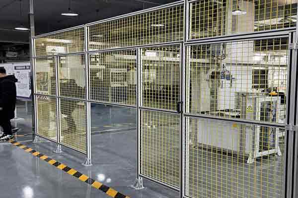
How to specify a bench so it cannot fail
Continuity is far cheaper to design in than to inspect in. Six lines in the purchase specification do most of the work.
- State the finish face by face. “Anodised on all visible faces, mill finish on slot faces and machined ends” is a normal, low-cost extrusion request. Left unsaid, the supplier anodises everything.
- Require electrical continuity of the frame. One sentence: all structural joints shall be electrically continuous, and any joint that is painted, coated or isolated shall be bridged with a 6 mm² bonding conductor. That single line moves the problem to the supplier, where it is cheap.
- Require a bonding point on every accessory. Light arms, monitor arms, tool rails, pegboards and drawer cabinets should each arrive with a stud or a masked land, so the field technician does not have to drill a painted surface to make the connection.
- Specify the ground cord properly. A 1 MΩ cord with crimped ring terminals and a bolted stud at each end. A crocodile clip is the most common single point of failure in a working ESD bench, because it works loose and nobody notices.
- Ask for a continuity record at shipment. The four-node readings for each bench, with date, temperature and humidity. This is a ten-minute job for a supplier who builds benches in a batch, and it gives you a commissioning baseline to compare against for the life of the bench.
- Order spare hardware with the bench. A handful of T-nuts, two bonding jumpers and a set of serrated washers. The failures happen when somebody adds an accessory in a hurry with whatever hardware is in the drawer.
The cost argument, in one line
A serrated washer costs a few cents and a 6 mm² jumper with two crimped ring terminals costs about a euro. A single reworked board in a batch of twenty costs more than the entire bonding kit for the bench that damaged it. This is not a close call.
Frequently asked questions
Does an ESD workbench frame have to be grounded?
Can I use anodised aluminium profiles for an ESD bench?
What resistance should the frame read?
How often should I test the bench?
Why does my mat pass but my bench fail?
Can I add a monitor arm or a tool rail to an ESD bench later?
Send us the bench layout and the ESD class
We extrude and machine the 20 through 60 series in 6063-T5, supply the brackets, T-nuts and bonding hardware, and can leave slot faces mill finish or mask bonding lands to order. Tell us the bench size, the equipment on it and the ESD class you have to hold, and we will come back with a frame specification that is buildable and testable.
Related reading
Twelve more engineering notes from this blog, picked for this article — plus every category below.
 Quality and InspectionGlobal Sourcing Excellence: Multi-Category OEM and ODM Manufacturing and Supply Chain Integration
 ApplicationsAluminium Profile Workbenches: Design the Top and the Frame as Two Separate Problems
 Engineering DesignWhat Is a 4040 Aluminium Profile? (Weight, Slot and Load)
 ApplicationsAluminium Partitions: The Three Performance Numbers Behind the Aesthetic
 Applications20 Series T-Slot Profiles: Where the Limits Actually Are
 Quality and InspectionAnodising vs Powder Coating: Thickness, Colour, Salt Spray
 ApplicationsAluminium Profile Display Boards: The Panel Is the Hard Part
 Engineering DesignAluminum Corner Brackets for T-Slot Frames: How to Choose by Load Path, Not by Looks
 Sourcing and ProcurementDistributor Terms: Territory, Margin and Price Protection
 Sourcing and ProcurementAuditing an Aluminium Profile Supplier: Factory, Trader, or Something in Between
 ApplicationsAluminium Profiles Across Industries: What Actually Changes From One Sector to the Next
 Machine SafetyAluminium Profile Machine Guards: Size the Frame from the Energy, Not from the Mesh
