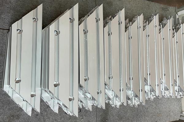
CNC Machined Aluminium Profile 40 x 40 mm Drilled and Tapped Cut List
40 x 40 mm aluminium profile supplied CNC machined to a cut list: saw cut, datum faces milled, holes drilled, threads tapped and edges deburred, then anodised if required.
| Material | Aluminium |
|---|---|
| Alloy Grade | 6063-T5 |
| Temper | T5 |
| Section Size | 40 x 40 mm, four slots |
| Slot | M6 slot, 8 mm mouth, four faces, 30 mm pitch |
| Length | Cut to list, +/-0.5 mm standard, +/-0.2 mm on request |
| Tolerance | Cut length +/-0.5 mm, hole position +/-0.2 mm, machined face 0.05 mm over 300 mm, section to EN 755-9 |
| Surface | Mill finish / clear anodised / black anodised, applied after machining |
| MOQ | No fixed minimum; jig cost dominates below a few hundred identical parts |
| Lead Time | 2 to 3 weeks for cutting, plus 1 to 2 weeks for machining, plus about a week for anodising; jig making adds 5 to 10 days on a first order |
| Loading Port | Shanghai / Ningbo |
| Supply Ability | In-house sawing, CNC machining, drilling, tapping, deburring and anodising under one roof |
| Payment Terms | T/T 30% deposit + 70% before shipment | L/C at sight |
| Trade Terms | FOB | CIF | EXW |
| Certifications | Dimensional report per lot, first article inspection report, mill certificate to EN 10204 3.1 on request, RoHS and REACH declarations |
01What can a machined aluminium profile actually hold?
Three different tolerances live on a machined 40 x 40 mm aluminium profile, and they come from three different operations. Confusing them is the root of most arguments about a batch that “does not fit”. The cut length comes from a saw, the hole pattern comes from a jig or a machining centre, and the section itself comes from the extrusion die — and the extrusion die is the loose one.
| Feature | Achievable tolerance | Comes from | What it costs |
|---|---|---|---|
| Cut length | +/-0.5 mm standard, +/-0.2 mm on a CNC saw | Saw and stop | Nothing extra up to +/-0.5 mm; +/-0.2 mm needs a slower cycle |
| Squareness of cut end | about 0.3 mm per 40 mm face | Saw blade and clamp | A double mitre saw is needed for better |
| Hole position along the profile | +/-0.2 mm | Jig or machining centre | A jig is cheap per part once it exists; the first part pays for it |
| Hole position across the profile | +/-0.2 mm, +/-0.05 mm on a machining centre | Fixturing and datum | Needs a machined datum face, which is a separate operation |
| Machined face flatness | 0.05 mm over 300 mm | Milling after extrusion | One extra operation per face |
| Section dimensions | wall +/-0.15 mm to EN 755-9 | The die | Nothing — it is what it is |
| Thread depth in the wall | 4 to 6 full threads, wall dependent | Wall thickness | Not a tolerance question at all |
Read that table the other way round and it becomes a design rule: anything tighter than the section tolerance cannot be referenced to the section. If a hole has to sit within 0.1 mm of a face, that face has to be machined first, and the hole is then located from the machined face. Without that sequence the tolerance is aspirational.
02Where does the datum come from?
Not from the extruded surface. An extruded face carries twist and bow that are entirely legal under the extrusion standard but far outside any machining tolerance, and a part located from that face inherits all of it. This is the single most common reason a first batch is rejected: the drawing dimensioned everything from a face that was never flat.
- Machine one or two adjacent faces and call them out as datum A and B. Two adjacent faces remove five of the six degrees of freedom and give a stable setup.
- Keep the machined face away from the slot mouth. Machining across the mouth leaves a burr inside the slot that a T-nut will find on the first assembly.
- Do not use the slot itself as a datum unless the drawing says which face of the groove, because the groove has two and they are not the same.
- For repeated parts, add a jig bore. One 6 mm hole machined in the same setup as the pattern becomes the reference for every subsequent operation, and it makes re-work possible instead of scrapping the part.
If the drawing has no datum callout at all, the shop will pick one — usually the most convenient face, which is the one that was extruded. Say which face is datum, or accept whatever the setup produced.
03How deep can you tap, and where?
This is where profile machining differs from machining a solid block. A 40 x 40 mm four slot section weighs between 1.30 and 2.35 kg/m depending on wall, which puts the standard wall at roughly 2 mm and the heavy wall at roughly 3.5 mm. Those are estimates from the mass, not drawing dimensions — check the actual section drawing before committing a thread.
| Where the thread goes | Available material | Practical thread | Use it for |
|---|---|---|---|
| Into a 2 mm standard wall | About 2 mm | M5 at most, and it is marginal | Nothing structural — a cover fixing at best |
| Into a 3.5 mm heavy wall | About 3.5 mm | M6, about 3 full threads | Light brackets, sensor mounts, cable clips |
| Into the O 12 mm centre bore | Full wall plus bore | M14 tapped, as standard | Through-bolting, levelling feet, end connections |
| Through a T-nut in the slot | Full nut depth | M6 or M8, full nut | Anything that carries load or is cycled |
| Through-bolt with a nut on the far face | Full section | M6 or M8 | The strongest joint available on this section |
The honest summary: a thread in a 2 mm wall is a location, not a fastening. It will hold a cover in place and it will strip the first time somebody over-tightens a bracket. Every load-bearing connection on this section should go through the slot with a T-nut, through the centre bore, or right through the section with a nut on the far side.
04What does batch consistency actually mean?
It means the 500th part is the same as the first, and it is a process question rather than a tolerance question. Four things drift across a batch, and each has a different control.
| What drifts | Symptom on assembly | Root cause | Control |
|---|---|---|---|
| Jig wear | Holes creep along the profile toward the end of the run | Bushes wear, clamps lose preload | Bushed jig with replaceable inserts, checked every few hundred parts |
| Tool wear | Hole diameter drifts small, tapping torque rises | Drill and tap wear | Tool life counter, and a mid-run gauge check |
| Thermal growth | Parts cut in the morning are a different length from afternoon parts | Shop temperature swing on a 6 m bar | Cut in a temperature-stable area, or measure and compensate |
| Setup shift between lots | A batch that fits, and the next batch that does not | The jig was re-set and not re-proven | First article approval on every re-setup, not just on the first order |
The control that actually works is boring: a first article inspection on every re-setup, with a signed dimensional report, and a sample check at the end of the run. It costs a few parts and it converts a whole class of complaints into a conversation about a report instead of a photograph.
05How should the drawing be prepared?
A cut list in a spreadsheet is enough for cutting only. The moment there are holes, the drawing has to carry them, and the format matters less than the content.
- Send DWG, DXF, STEP, IGES or PDF. We work in all five. A STEP model plus a PDF with the tolerances is the combination that produces the fewest questions.
- Give one drawing per part number, not one drawing with a table of variants. Variants in a table are where the wrong hole pattern gets drilled.
- State the datum faces explicitly with a datum symbol, and say whether they are as-extruded or machined.
- Dimension hole positions from the datum end, not from both ends. Two reference ends means two tolerances stacking.
- Say what the part does. “Bracket fixing” and “guard panel fixing” produce different decisions about thread depth and edge distance, and a shop that knows the function will flag a bad callout instead of building it.
- Mark the visible faces. It decides which face gets the machining marks and which face may be used for clamping.
06How is deburring done, and what does it cost?
Every cut and every drilled hole leaves a burr, and on an anodised part a burr is worse than a cosmetic problem — it holds moisture and it cuts the operator. There are four routes and they are not interchangeable.
| Method | Result | Good for | Limitation |
|---|---|---|---|
| Hand deburr | Removes the sharp edge, leaves a visible witness mark | Small batches, one-off frames | Operator dependent, slow, inconsistent |
| Brush / abrasive wheel | Uniform edge break, slight surface sheen | Straight cut ends in volume | Only reaches the outside of the section |
| Vibratory finishing | Fully rounded edge, all over | Loose parts in volume | Cannot be used on long lengths, and it moves dimensions slightly |
| Thermal deburr | Burns the burr away, no mechanical contact | Complex internal intersections | Leaves a thin oxide film that has to be removed before anodising |
For a 40 x 40 frame kit the practical answer is brush deburr on the cut ends plus a quick hand pass on drilled holes. That is what most kits ship with. If the parts go for anodising, the deburr has to happen first, because anodising does not hide a burr — it makes it permanent.
07What should not be sent to a profile shop?
There is a category of work where an extrusion-based supplier is the wrong choice, and saying so early saves a rejected batch.
- Tight true-position patterns in thin walls. A bolt circle held to 0.05 mm in a 2 mm wall will move when the part is clamped for machining and move again when it is released. Use a machined plate.
- Deep bores. A bore more than a few diameters deep in an aluminium profile is a specialist operation with a boring bar, not a drilling operation.
- Flatness on a large as-extruded face. If the requirement is a flat plate, start from plate.
- Threads below M5 in a 2 mm wall. There is not enough material for the thread to survive a torque wrench.
- Welded assemblies that must then be anodised. The weld pool is a different alloy from the extrusion, and it anodises to a different colour every time. Bolt it instead.
- Anything needing a material certificate for a specific heat number unless that is raised at enquiry — traceability to heat number is available but it changes the purchasing route.
Cut list and drawing checklist
- One drawing per part number, with the revision letter visible
- Datum faces marked, and whether they are machined or as-extruded
- Hole positions dimensioned from a single datum end
- Thread sizes and depths, or the fixing type if you want a recommendation
- Which faces are visible, and which may be used for clamping
- Deburr requirement: edge break only, or fully rounded
- Finish, and whether it is applied before or after machining
- First article approval required — yes or no
- Packing: kit per assembly, or loose by part number
08Questions from design and purchasing
Related sections and categories
Browse CNC Machining, 40 Series Aluminium Profiles, the 40 x 40 mm four slot section for the base section data, or the framing kit with a cut list if the whole frame is being bought as one package.
What tolerance can you hold on a drilled hole in a 40 x 40 profile?
+/-0.2 mm on position is standard from a jig. +/-0.05 mm is possible on a machining centre, but only if the hole is located from a machined datum face rather than from the extruded surface.
Do you machine the profiles yourselves?
Yes. Extrusion, saw cutting, datum face machining, drilling, tapping, counterboring and deburring are in house, and anodising follows in the same plant, so the sequence is controlled rather than handed between suppliers.
What is the minimum order for machined profiles?
There is no fixed minimum, but the economics change at the point where a jig is needed. Below a few hundred identical parts the jig cost dominates and hand setup is cheaper; above that the jig pays for itself quickly.
Can you work from a STEP model only?
Yes, but send a PDF with the tolerances as well. A model carries nominal geometry and no tolerance, and tolerance is the part of the job that decides whether the batch is accepted.
What happens if the first article is out of tolerance?
It is corrected before the run continues. That is the point of first article approval: the cost of a correction at article one is a few parts, and the cost at article five hundred is the whole batch.
Do you supply a dimensional report?
Yes, per lot, covering cut length, hole position, thread gauge where tapped, and machined face flatness where specified. A full CMM report is available on request.
What to send for a machined profile quote
- Cut list: part number, profile, length, quantity
- Drawing per part number in DWG, DXF, STEP, IGES or PDF
- Datum faces and whether they are to be machined
- Hole pattern with positions, diameters and thread callouts
- Deburr requirement and any edge radius
- Finish and the order of operations, if anodising or coating is involved
- Whether first article approval and a dimensional report are required
- How the parts are packed: by assembly kit or loose by part number
- Target date, because jig making sits on the critical path
The single most useful thing on an enquiry is a note about what the part does. It lets us flag a callout that cannot be held before the batch is made, rather than after.
Send the cut list and one drawing
A cut list plus a single part drawing is enough for us to quote. Tell us what the part does and which faces are seen, and we will flag any callout that cannot be held before the batch is made.
Request a quotationRelated Products
 Aluminium Profile Hinge 40 Series 180 Degree for 8 mm Slot Guard Doors
180 degree hinge for 40 series aluminium profile guard doors. Two leaves clamp into…
 Aluminium Profile Sliding Door 40 Series 8 mm Slot for Machine Enclosures
Sliding door leaves framed in 40 series aluminium profile for machine enclosures. Top hung…
 ESD Aluminium Profile Workbench 40 x 40 mm Anti-Static Assembly Frame
ESD workbench built on a 40 x 40 mm aluminium profile frame, supplied mill…
 Aluminium Profile Stair Stringer 45 x 90 mm for Access Platforms
45 x 90 mm six slot heavy aluminium profile at about 4.85 kg/m, cut…
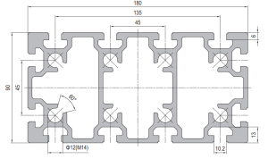 Aluminium Profile CNC Router Gantry 90 x 180 mm Twelve Slot Beam
90 x 180 mm twelve slot aluminium profile at about 9.50 kg/m for a…
 Aluminium Profile Truck Body Frame 50 x 100 mm for Dry Freight Boxes
50 x 100 mm six slot aluminium profile at about 5.40 kg/m for dry…
 Solar Mounting Aluminium Rail 45 x 45 mm for PV Array Frames
45 x 45 mm four slot aluminium profile at about 2.55 kg/m, used as…
 Aluminium Profile for Sale: 45 x 60 mm Cut to Length, No Minimum Run
45 x 60 mm aluminium profile in 6063-T5, sold by the length or by…
