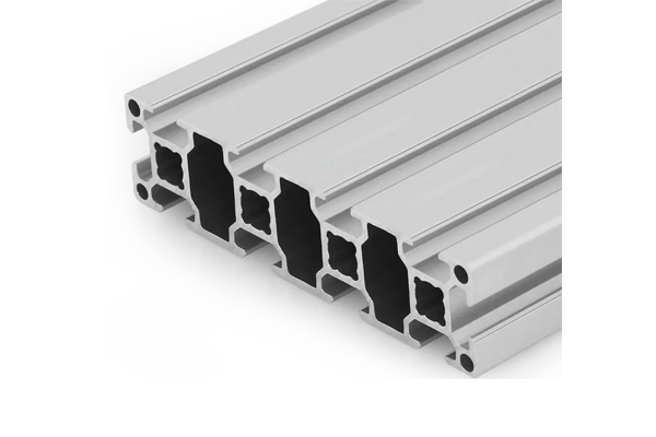
30 x 120 mm Aluminium Profile for Heavy Equipment Frames
30 x 120 mm ten-slot aluminium extrusion in 6063-T5 for construction equipment guards, platform edges and attachment frames. 2.70 kg/m, with an axis ratio of about nine to one that has to be designed for.
| Material | Aluminium |
|---|---|
| Alloy Grade | 6063-T5 |
| Temper | T5 |
| Section Size | 120 x 30 mm, ten slots |
| Slot | 10 x 8.2 mm groove, 6 mm mouth, 30 mm pitch, outer pair 90 mm apart, M6 |
| Length | 6 m stock; cut to list to +/-0.5 mm |
| Tolerance | EN 755-9, wall +/-0.15 mm; straightness 1.5 mm per metre; twist 2 degrees |
| Surface | Mill finish, or anodised AA15 to EN ISO 7599; clear or black |
| MOQ | 150 m |
| Lead Time | 20 to 28 days after deposit for mill finish, about one week longer for anodising |
| Loading Port | Shanghai / Ningbo |
| Supply Ability | 600 t per month extrusion with in-house anodising |
| Payment Terms | T/T 30% deposit + 70% before shipment | L/C at sight |
| Trade Terms | FOB | CIF | EXW |
| Certifications | Mill certificate per heat, coating report per lot, RoHS and REACH declarations |
01What dynamic factor does an attachment actually see?
Not 1.0, and that is the whole point. A static calculation on a construction equipment frame tells you what happens when the machine is parked. In service the load arrives with an impact, a reversal and a repetition, and the design has to carry all three.
For most attachments the dynamic factor sits between 1.3 and 1.8 on the nominal load, and for a bucket or a breaker it can be higher on the individual shock peaks. The factor is applied to the load, not to the allowable stress, which is the mistake that produces a frame that passes the calculation and cracks in the first season.
| Application | Dynamic factor | What it covers |
|---|---|---|
| Static guard or railing | 1.0 to 1.2 | Wind and occasional contact |
| Platform edge or walkway | 1.3 to 1.5 | Foot traffic and tool drops |
| Attachment bracket, general | 1.5 to 1.8 | Reversing load plus impact |
| Bucket, breaker or hammer mount | 2.0 and above on shock peaks | Impact, plus a fatigue check |
A dynamic factor is not a safety factor. The safety factor sits on top of it, against yield or against the fatigue limit. Multiplying by 1.5 and calling it done leaves the fatigue case uncovered, and fatigue is what actually fails these frames.
02Why is the weak axis the design axis for a 30 x 120?
Because the section is nine times stiffer one way than the other. For a 30 x 120 box with a 2.5 mm nominal wall, the second moment about the strong axis is roughly 115 cm4 and about the weak axis roughly 12 cm4. A load applied sideways, which is exactly what a side impact or a diagonal brace reaction produces, sees the 12.
That ratio is the whole engineering story of this section. It is excellent as a rail, a platform edge or a guard where the load is vertical and the depth does the work. It is poor as a column or as anything that has to resist a lateral push, unless the lateral direction is restrained by bracing or by the way it is fixed.
Loaded on the 120 mm face
- Second moment about 115 cm4
- Deflects like a proper beam
- Suits rails, edges and platform members
- The intended use of the section
Loaded on the 30 mm face
- Second moment about 12 cm4, roughly one tenth
- Deflects like a strip, and buckles early in compression
- Needs bracing or a change of section
- The failure mode people miss on site
03What does welding cost in strength terms?
About 40 to 50 percent in the heat affected zone. Welding 6063-T5 takes the material through a thermal cycle that overages the precipitates in the zone beside the weld, and the strength there falls to roughly the annealed value. No amount of post-weld ageing restores it without a full solution treatment, which is not practical on an assembled frame.
The consequence is that a welded joint is not a T5 joint. If the design assumed the parent metal strength, the weld becomes the weak link by a factor of nearly two, and it is also where the fatigue crack starts, because the weld toe is a stress raiser and often contains a small defect.
- Design the welded joint for roughly half the parent metal strength, or increase the section locally, or do not weld.
- If welding is unavoidable, put the weld away from the highest bending moment, not at the corner where it is easiest to make.
- A full penetration weld is not automatically better here; the heat input is higher and the affected zone is wider. A fillet with the right throat is often the better detail.
- State the welding on the enquiry. A frame designed as bolted and welded on site has a strength assumption that nobody checked.
04What does the stress range do over a million cycles?
Aluminium has no endurance limit in the way steel does. The S-N curve keeps falling, so the design has to be against a stated number of cycles rather than against a stress below which nothing happens. For welded aluminium details, the relevant curves are the ones in Eurocode 9, and they are considerably lower than the parent metal curve.
A practical consequence: a bracket that sees a 20 MPa stress range at 2 million cycles is fine in parent metal and marginal at a weld toe. The same geometry, same load, different detail, different life. This is why the joint design matters more than the section on a vibrating machine.
| Detail | Relative fatigue performance | Comment |
|---|---|---|
| Parent metal, no joint | Reference | Rarely the critical location |
| Bolted joint with preload | Good if preload is maintained | Fails by fretting if preload drops |
| Welded toe, transverse | Much lower | Stress raiser plus possible defect |
| Welded toe, longitudinal | Lower still | Often overlooked |
| Sharp change of section | Low | A machined radius is cheaper than a repair |
05Bolted or welded under vibration?
Bolted, in almost every case where the frame has to be serviceable, and for a reason that has nothing to do with strength: a bolted joint can be inspected, re-torqued and replaced. A welded joint can only be cut out. On plant equipment, where the machine is repaired rather than replaced, that difference decides the maintenance cost.
The bolted joint’s weakness is preload loss, which is manageable with hardened washers and a re-torque schedule. The welded joint’s weakness is a strength reduction that cannot be recovered and a fatigue detail that cannot be improved after the fact.
Bolted joint checklist for a vibrating frame
- Hardened washer under head and nut, so the aluminium does not yield and lose preload.
- Connector engaging both slot flanges, not a single central bolt.
- Re-torque at 100 hours, then at the first service interval.
- Dry joint, no lubricant, because lubricant lowers the friction coefficient and the slip resistance with it.
- Record the torque figure on the drawing, so the next rebuild uses the same number.
06What five numbers should be on the enquiry?
For a dynamic application the numbers are the load, the direction, the cycles and the joint. The direction is the one that decides whether this section is suitable at all.
- Nominal load and direction
- magnitude, and whether it acts on the 120 mm face or the 30 mm face
- Dynamic factor
- the one your application standard requires, stated explicitly
- Cycles in service
- per year or over life, because aluminium has no endurance limit
- Joint type
- bolted or welded, and if welded, where the weld sits relative to the moment
- Span and restraint
- clear span, and whether the weak axis is braced
- Section
- 30 x 120 mm ten slot at 2.70 kg/m, or 40 x 120 at 4.60 kg/m if the weak axis governs
Send the load direction and the cycles
- 30 x 120 mm, 6063-T5, ten 8.2 mm slots, 2.70 kg/m
- 180 m cut to the frame list, holes on drawing
- Mill finish, or AA15 anodised for exposed faces
- Load direction and dynamic factor stated
- Joint detail attached, bolted or welded
Tell us which face takes the load. A 30 x 120 loaded on the 30 mm face has about a tenth of the stiffness, and no amount of extra wall thickness in the same envelope fixes that.
Related sections and categories
The 30 x 120 is listed under 30 Series Aluminium Profiles. Where the weak axis governs, the 40 x 120 mm eight slot section at 4.60 kg/m is the direct step up, and the joint hardware is under joining plates.
Is 30 x 120 strong enough for a construction equipment guard?
For a guard or a platform edge loaded on the 120 mm face, yes. The second moment about the strong axis is roughly 115 cm4, which is a real beam. The problem is the weak axis: about 12 cm4, roughly one tenth, so any lateral load has to be braced or the section has to change. State the load direction on the enquiry rather than the section.
What dynamic factor should I apply?
Between 1.3 and 1.8 for most attachments, and higher on shock peaks for a bucket or a breaker. Apply it to the load, not to the allowable stress, and then apply a separate safety factor on top. Multiplying by 1.5 and stopping there leaves the fatigue case uncovered, which is the case that usually governs.
How much strength is lost if the frame is welded?
Roughly 40 to 50 percent in the heat affected zone. Welding 6063-T5 overages the precipitates beside the weld and the strength there falls towards the annealed value. Post-weld ageing does not restore it without a full solution treatment. Design the welded joint for about half the parent metal strength, or bolt it instead.
Why does aluminium fatigue differently from steel?
Because it has no endurance limit. The S-N curve keeps falling with cycles, so the design has to be against a stated number of cycles rather than against a stress below which nothing happens. For welded details the relevant curves are well below the parent metal curve, which is why the joint detail often governs the life.
Can the frame be repaired on site?
A bolted frame can be, which is the main argument for bolting on plant equipment. Members are replaceable, joints can be re-torqued and the alignment can be reset. A welded frame has to be cut out and re-welded, which loses more strength each time and cannot be done without affecting the surrounding material.
Send the load direction and the cycle count
Give us the nominal load, which face it acts on, the dynamic factor your standard requires and the cycles per year. We will check the weak axis before we recommend a section.
Request a quotationRelated Products
 90 x 90 mm Aluminium Profile Supply: Stock Planning and Lead Time
90 x 90 mm eight-slot aluminium extrusion in 6063-T5 for multi-site supply across Maharashtra.…
 50 x 50 mm Aluminium Profile for Precision and Aerospace Fixtures
50 x 50 mm four-slot aluminium extrusion in 6063-T5 for inspection and assembly fixtures.…
 45 x 60 mm Aluminium Profile Solutions for Windows and Facades
45 x 60 mm four-slot aluminium extrusion in 6063-T5 for shopfront, screen and facade…
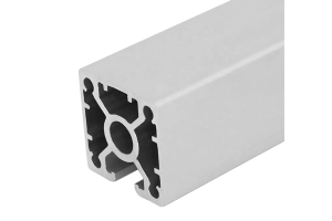 40 x 40 mm Light Aluminium Profile for Mining Equipment
40 x 40 mm four-slot aluminium extrusion in 6063-T5 from 1.30 kg/m, for guards…
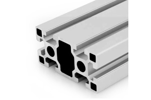 Custom 45 x 90 mm Aluminium Extrusion: Dies, Tooling and Lead Time
45 x 90 mm six-slot aluminium extrusion in 6063-T5 from a China plant. 4.10…
 T-Slot Reducing Profile
Reducing insert that narrows a wide T-slot to accept standard nuts and accessories from…
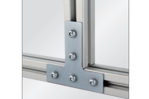 Joining Plate PG30 (3030)
L-shaped joining plate that bolts into the 30 series T-slot to make a 90°…
 Strut Aluminium Profile 40×40 mm 4-Slot T-Slot Extrusion Machine Frame
40 x 40 mm four-slot T-slot strut aluminium profile in 6063-T5 with M6 slots…
