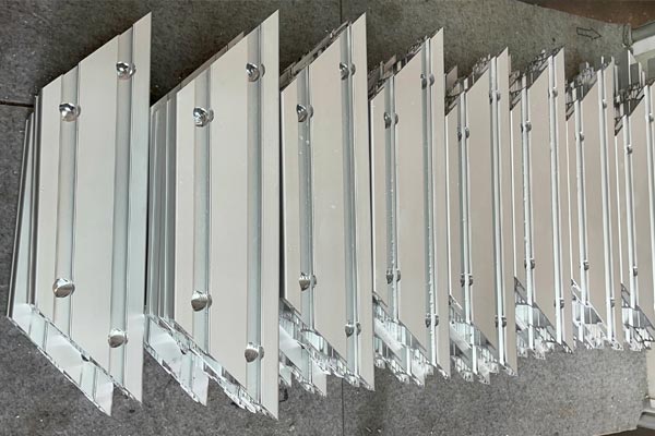
There is a particular kind of argument that happens on a loading dock. A pallet of extruded profiles has arrived. The drawing says ±0.10 mm on the slot width. The caliper reads 0.14 mm over. The supplier’s inspector says the goods are within tolerance. Your inspector says they are not. Both are reading the same document, and the document does not resolve the dispute, because it never said how the measurement was to be taken.
This article is about closing that gap. Most guides to extrusion tolerances, including the good ones, explain the categories and tell you to specify a standard. That advice is correct and incomplete. What determines whether an inspection is worth doing is three things the categories never address: whether the measurement method is defined, whether the gauge is capable of the tolerance you wrote, and whether temperature effects have been accounted for. Get those three right and the argument on the dock disappears.
It is written for the person who has to sign the incoming inspection record, not the person who designs the profile. There is a first-article inspection format, a measurement procedure for each tolerance type, a concession process for marginal goods, and a supplier scorecard at the end. Take what is useful and delete the rest.
About the values
One honest caveat about numbers. Tolerance values quoted below are indicative magnitudes, given so you can see the scale and sanity-check a supplier’s claim. The standard you name on the drawing is the authority, and standards are revised — quote the edition year and read the current table. The measurement methods and the temperature arithmetic, however, are physics and do not change with the edition.
Quick answer
Nine things to settle before the first shipment arrives
Each is expanded below. If you are short of time, the temperature point (item 3) and the gauge capability point (item 4) are the two that most often decide whether an inspection is meaningful at all.
The tolerance that causes most rejections is the one nobody measured Slot width and wall thickness at the slot govern whether T-slot hardware clamps. Give them their own limit — typically ±0.10 mm — and list them on the PO, not only on the drawing.
Name the standard and its edition year “Per EN 755-9” is ambiguous. “Per EN 755-9:2016, class normal” is a specification. For tight work, EN 12020-2 is the precision-profile standard.
Temperature is a real tolerance, not a rounding error Aluminium expands at about 23.1 µm/m·K. On a 6 m profile, a 5 °C difference between the part and the gauge is 0.69 mm of apparent error. Length is measured at a reference temperature of 20 °C.
Your gauge is probably not capable of the tolerance you wrote A 0.01 mm caliper resolution is not a 0.01 mm measurement uncertainty. As a rule of thumb, do not specify a tolerance tighter than ten times the realistic measurement uncertainty of the method you will use.
Straightness and twist need a defined method, not a defined opinion Support the profile, define the reference length, and state whether the limit is per metre or over the full length. Without that, two competent inspectors will reach different verdicts.
Separate extrusion tolerance from machining tolerance An extruded slot holds one class of tolerance; a milled slot holds another. If a feature needs the tighter class, put it in the machining scope and inspect it as a machined feature.
Require a first-article inspection report before mass production Dimensional results, the measurement method used, gauge identification, the datum, and photographs. Approving a FAIR is the cheapest quality control you will ever buy.
Decide the marginal case in advance A documented concession process with a credit formula removes the improvisation that turns a 0.04 mm overshoot into a month-long dispute.
Feed dimensional data back as process information Trends in wall thickness and twist point at die wear, billet temperature and quench balance. A supplier who receives that data fixes the cause; a supplier who receives only rejections fixes nothing.
Taxonomy
The tolerance types, with the magnitudes that matter
Extruded profile tolerances fall into two families, and confusing them is the source of a lot of unnecessary dispute. The first family is set by the extrusion process itself: cross-sectional dimensions, wall thickness, straightness, twist and length. The second family is created by whatever you do to the profile afterwards: cutting, milling, drilling and tapping. They behave differently, they are measured differently, and they should be specified in different places on your documentation.
Cross-sectional dimensions
The tolerance on a cross-sectional dimension is not a single number. It varies with the size of the dimension itself, and it varies with the class you specify. The structure of every standard table is the same: dimension bands on one axis, tolerance class on the other, with the tolerance growing as the dimension grows. As an indication of scale, for a normal class on industrial profiles, you should expect roughly ±0.2 mm on dimensions up to about 10 mm, rising through ±0.35 mm around 50 mm and ±0.5 mm or more beyond 100 mm.
The single most important consequence
Notice what those numbers mean for T-slot hardware. If a slot is nominally 8 mm wide and the general cross-sectional tolerance for that dimension band is around ±0.2 mm, then a slot at 8.2 mm is technically conforming and the T-nut will be loose. This is exactly why slot dimensions must be lifted out of the general table and given their own critical limit on the purchase order. A general tolerance will not protect a functional fit.
Wall thickness
Wall thickness tolerance is generally looser than cross-sectional dimension tolerance, because wall thickness is governed by metal flow through the die rather than by the die’s machined dimensions. It is also the characteristic most sensitive to extrusion speed and billet temperature. The consequence is practical: if a wall must be a specific thickness for a thread or a bearing surface, do not rely on the extrusion tolerance — leave material and machine it.
Straightness
Straightness limits are normally expressed either as a deviation over a reference length or as a total deviation over the full length, and the two give very different numbers. A limit of 0.5 mm over 300 mm is not the same as 0.5 mm over 6,000 mm. Most standards use a combination: a per-unit limit plus a maximum total. If your drawing does not say which applies, expect the looser interpretation to be used.
Twist
Twist is a rotation about the longitudinal axis, and it is the tolerance most often omitted from drawings and most often the cause of an assembly that will not close square. Like straightness, it scales with length, so the limit must state whether it is per metre or total. Twist is also the characteristic that reveals an unbalanced die or an uneven quench, which makes it a useful process indicator rather than just a pass or fail gate.
Cut length
Cut length is a post-extrusion operation, so its tolerance depends on the method: a stop-cut on a saw typically holds around ±0.5 mm, a machined end can hold ±0.2 mm or better. Critically, cut length is where the temperature effect is largest, because it is the only dimension measured over the full length of the profile. That point deserves its own section, and it gets one below.
Machined features
Holes, threads, counterbores and milled faces should be specified to a machining standard and located with a positional tolerance rather than a chain of linear dimensions. This matters because a dimension chain accumulates error from the datum, while a positional tolerance controls the pattern as a whole. If you find yourself adding up three dimensions to work out whether a hole is in the right place, the drawing is telling you the wrong thing.
Method
How to actually measure each one
This is the section most tolerance guides skip, and it is the one that prevents dock arguments. A tolerance without a stated method is an opinion. Write the method into the inspection plan and both parties will get the same answer.
Two administrative habits make all of this enforceable. First, record the gauge identification on every inspection record, so a result can be traced back to the instrument that produced it and its calibration status. Second, record the method actually used, not the method intended. When a dispute reaches the point of comparing records, the difference between the two is usually the whole argument.
Measurement error
Why temperature can be bigger than your tolerance
This is the point that most inspection procedures miss, and it is not a theoretical concern. Aluminium has a coefficient of thermal expansion of about 23.1 micrometres per metre per kelvin. Multiply that by the length you are measuring and you get the length change per degree:
ΔL = L × α × ΔT
ΔL = 6,000 mm × 23.1×10⁻⁶ /K × 5 K = 0.69 mm
A 6-metre aluminium profile that is 5 °C warmer or colder than the gauge used to measure it will appear to be 0.69 mm longer or shorter than it is. For comparison, a typical stop-cut length tolerance is around ±0.5 mm. The measurement uncertainty from temperature alone is larger than the tolerance being checked.
The same arithmetic applies to cross-sectional dimensions, but at a much smaller scale, which is why nobody notices it there. A 40 mm dimension changes by 40 × 23.1×10⁻⁶ × 5 = 0.0046 mm over 5 °C. That is below the resolution of the caliper. So the effect is invisible on the section and decisive on the length, and that asymmetry is exactly why it catches inspectors out.
What to do about it, practically
State the reference temperature
Dimensional measurements are conventionally referenced to 20 °C. Put that on the inspection plan so both parties are working to the same baseline.
Let the material equalise before measuring
A profile that has just come off a truck in winter, or out of a sun-exposed container in summer, is not at ambient. Let it stabilise before you measure length, and record how long it was left.
Record the temperature on the inspection record
Ambient and, if you have it, surface temperature. Two records with different temperatures are not comparable, and knowing that prevents a false non-conformance.
Correct, or widen, the length tolerance
Either apply the arithmetic correction when the measured temperature differs from the reference, or state a length tolerance that is wide enough to absorb the temperature range you will actually measure in. Pretending the effect is not there is the one option that does not work.
The related trap: gauge capability
Temperature is the largest single error source, but gauge capability is the most common. A digital caliper with a 0.01 mm resolution does not measure to 0.01 mm. Its realistic uncertainty on a smooth extruded surface is several times that, worse on a coated or anodised surface where contact geometry is inconsistent, and much worse when the feature is difficult to access.
The working rule is that a measurement method should be capable of resolving about one tenth of the tolerance it is checking. If you specify ±0.10 mm on a slot width and your only instrument is a hand-held caliper, you have specified a tolerance you cannot verify. Either buy the right gauge — a slot gauge or a dedicated plug gauge for the slot — or specify a tolerance you can actually hold the supplier to.
A note on unverifiable tolerances
This cuts both ways and is worth saying plainly to a supplier. If you cannot measure a dimension reliably, you cannot reject material on it. Writing a tight tolerance you cannot verify does not improve quality; it just makes every inspection inconclusive and trains everyone to ignore the result.
Approval gate
The first-article inspection report
Mass production should never start on a new profile until a first article has been measured and approved. The first article is the piece that proves the die, the fixture and the process can hold the drawing together. If the die is going to be wrong, it will be wrong on the first article, and finding out then costs a trial run instead of a container.
Require the report to contain the following, and make approval of it a condition of proceeding to volume:
Approve the article, retain it, and label it. When a dispute arises six months later about whether the process has drifted, the retained first article is the reference that settles it, in the same way that a retained colour sample settles a finish argument.
Non-conformance
What to do when the goods are marginal
The hardest decision in incoming inspection is not the clear pass or the clear fail. It is the 0.14 mm reading against a ±0.10 mm limit on a shipment your production line needs next week. Handled improvidently, that decision consumes more management time than the defect is worth. Handled with a process, it takes twenty minutes.
Three outcomes, defined in advance
Accept as-is, with a concession
The deviation has no functional consequence for this application. Record it as a formal concession against the lot, with the buyer’s engineering signature, and apply the pre-agreed credit formula. Do not simply absorb it — an unrecorded concession becomes a permanent loosening of the specification.
Rework or sort
The deviation can be corrected by machining, or the lot can be sorted into conforming and non-conforming portions. Agree in advance who pays, where the work happens, and how the sorted material is identified. Sorting at your own facility should carry a charge-back.
Reject the lot
The deviation is functional or safety-related, or it is a repeat of a previously conceded issue. Rejection at the factory is far cheaper than rejection at your dock, which is the argument for pre-shipment inspection in the first place.
The credit formula
A concession is much easier to negotiate when the number is already agreed. A workable structure is a credit proportional to the fraction of the tolerance band consumed by the deviation, capped at a proportion of the line value, with a floor below which the deviation is treated as acceptable and no credit is applied. The exact percentages matter less than the fact that both parties agreed them before the first shipment. What you are buying with the formula is not money; it is the absence of a negotiation every time a marginal lot arrives.
The slow-motion failure
Watch for the pattern, not the individual event. A single marginal lot is normal manufacturing variation. The same characteristic drifting marginal across three consecutive lots is a process problem — usually die wear or a temperature control issue — and accepting it three times in a row converts it into your new specification by default. Track it, and raise it as a corrective action request rather than as another concession.
Continuous improvement
Turning inspection data into process feedback
An inspection that produces only pass or fail has thrown away most of its value. Dimensional data has a shape, and the shape points at the cause. Suppliers who receive this information fix problems; suppliers who receive only rejections ship the same goods again with better paperwork.
| Observed pattern | Likely process cause | Useful request to the supplier |
|---|---|---|
| Wall thickness trending thin over a production run | Die wear, or extrusion speed increased to raise output | Confirm die hours since last refurbishment; confirm the speed set point |
| Twist increasing along the length | Unbalanced die, uneven quench, or asymmetric cooling on the run-out table | Review quench balance and cooling arrangement |
| Straightness varying between bundles | Stretching operation inconsistency, or handling after stretching | Confirm stretching parameters and bundle handling method |
| Cross-section drifting on one dimension only | Localised die wear or a bearing problem on that face | Request die measurement data for the affected face |
| Cut length spread larger than the stated tolerance | Saw stop wear, or measurement at a different temperature | Confirm saw calibration and the temperature at cutting |
| Surface defects clustered at one end of the bar | Billet skin or lubricant issue at the start of the press stroke | Request the cut-off allowance and discard practice |
This is the table to send with a corrective action request. It converts a complaint into a technical conversation, which is the only kind that produces a change.
A supplier scorecard that changes behaviour
Four metrics, reviewed quarterly, are enough to manage an extrusion supplier. More than four and nobody looks at them.
- Defective parts per million, split by defect class. Splitting by class matters, because a cosmetic scratch and an out-of-tolerance slot should never be averaged into one number.
- First-article first-pass yield. How often a new profile or a new die is approved without a second submission. This is the best single predictor of how a supplier will behave on a new project.
- Concession rate. The proportion of lots accepted with a deviation. A rising rate means the specification is drifting, regardless of how good the individual decisions were.
- Corrective action closure time. How long between raising a non-conformance and receiving evidence that the cause was addressed. This is the metric that separates a partner from a vendor.
Run those four for a year and you will know more about your extrusion supply base than any audit will tell you. They also give you something concrete to discuss at a business review, which is where quality improvements actually get funded.
FAQ
Frequently asked questions
Inspect against a stated tolerance
The items this inspection plan is written around
An inspection plan is only as good as the tolerance it references. Each archive below covers the tolerance class, the inspection routine and the report that ships with the batch.
Ask us for the inspection data before you order
We hold slot and fit dimensions to a controlled limit, machine secondary features in-house, and supply a first article inspection report with every new profile. Send a drawing and we will tell you what we can hold.
Related reading
Twelve more engineering notes from this blog, picked for this article — plus every category below.
 Engineering DesignAluminium Profile Anchor Pins: A Preloaded Joint, Not a Pin
 Quality and InspectionT-Slot Aluminium Profiles for Industrial Frames and Automation: A Specification Playbook
 Engineering DesignAluminium Extrusion Tolerances: What to Write, and How to Inspect
 ApplicationsCleanroom and Medical Framing: There Is No Medical-Grade Aluminium Extrusion
 ApplicationsAluminium Profile for LED Strips: A Heat Sink First, a Housing Second
 Quality and InspectionSampling and First Article Approval for Aluminium Extrusion
 Materials and EngineeringAnodised vs Powder Coated Aluminium Profiles: A Specification Guide for European Buyers
 Engineering DesignAluminium Profile Standard Sizes: How the Series Matrix Actually Works
 Sourcing and ProcurementAluminium Profile Shipping: Packing, Container Loading and ISPM 15
 ApplicationsWhere Modular Aluminium Framing Works: A Load-Tier Map Instead of an Industry List
 Sourcing and ProcurementAluminium Profile Price Breaks: How Volume Changes the Unit Price
 ApplicationsWhy T-Slot Aluminium Profiles Are Used in Automation and When They Are Not
