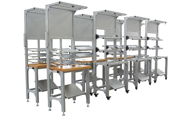
An anodised aluminium profile is an electrical insulator. Not a poor conductor, not a high-resistance path — an insulator, with a surface resistivity comfortably above 10¹¹ ohms. Which means that a workbench frame built from anodised aluminium profiles, however handsome it looks in the catalogue, is not an anti-static bench. It is a bench made of an insulator.
This is not a small technicality. It is the single most common misunderstanding in ESD-protected area fit-out, and it explains a particular pattern of audit finding: a production line full of expensive aluminium workstations, all of them described as anti-static, and an auditor standing in the middle of it writing up a major non-conformance. The frames are not the only problem — there are usually plastic totes and paper binders involved too — but the frames are the part everyone assumed was fine.
This article is written for the facility or process engineer who has to own the ESD control plan. It covers what the resistance numbers actually are, what makes a bench dissipative rather than merely metallic-looking, how to ground it properly, how to measure it, and the eight things that get written up most often. It is not a substitute for the standards themselves, and it assumes you will read ANSI/ESD S20.20 and S6.1 alongside it.
Two different meanings
One clarification that prevents a lot of confusion. “Anti-static” in the marketing sense means “does not generate or hold a static charge”. In the standards sense it means the material falls inside a defined resistance window, measured by a defined method, at a defined test voltage. Only the second definition survives an audit.
Quick answer
Nine points that decide whether the bench passes
If you read nothing else, read items 1, 2 and 8. The first two explain why a standard profile bench is not what it claims to be; the eighth explains why the real offender is usually something sitting on the bench rather than the bench itself.
Anodising is a dielectric, not a conductor The anodic layer on aluminium is aluminium oxide, an excellent insulator. Standard anodising gives a surface resistivity above 10¹¹ Ω — firmly in the insulative band.
The target is static dissipative, not conductive ESD-protected areas generally work with materials in the 10⁴ to below 10¹¹ Ω band, and practically in the 10⁶ to 10⁹ Ω range for work surfaces and flooring.
Three classes, one threshold each Conductive below 10⁴ Ω, static dissipative from 10⁴ to below 10¹¹ Ω, insulative at 10¹¹ Ω and above.
A bench is ESD-safe because of four things, not one The work surface, the ground path, the fasteners and accessories, and the personnel grounding method. Get three and miss one and the bench fails.
If the frame must be dissipative, change the finish Chromate conversion coating, conductive anodising, electroless nickel or conductive powder coating. Ordinary anodising cannot be made dissipative by grounding it.
Wrist straps need 1 MΩ for safety The resistor is there to limit current if the operator contacts live voltage. It is a personnel safety device, not an ESD nicety.
Measure with the right electrode and the right voltage A 5 lb (2.27 kg) electrode per the surface resistance test method, at 10 V below 10⁶ Ω and 100 V at or above it.
Insulators cannot be grounded This is why the plastic tote, the foam insert, the paper binder and the polystyrene cup matter more than the frame. Remove them or neutralise them with an ioniser.
Use the slot to carry the ground path This is the genuine advantage of a profile bench: the T-slot is a protected route for the bonding conductor, and the bench can be reconfigured without breaking ground continuity.
The core problem
The counter-intuitive part: why anodised aluminium is not the answer
Anodising is an electrochemical process that grows a controlled oxide layer on the aluminium surface. That is exactly what makes it valuable: the oxide is hard, it resists corrosion, it takes dye evenly, and it does not flake off like a paint. It is also, electrically, a ceramic. Aluminium oxide has a band gap of around 8 electron volts, which is to say it is one of the better insulators available in a workshop.
So the anodic layer that makes an aluminium profile durable is the same layer that makes it useless as a grounding path. A typical anodised industrial profile presents a surface resistivity well above 10¹¹ Ω, and the layer is thick enough and continuous enough that bolting it to a grounded steel frame does not fix it. The fastener may be bonded; the surface that a component or an operator’s hand actually touches is not.
Standard anodised aluminium: surface resistivity > 10¹¹ Ω → insulative
Required for an ESD work surface: 10⁶ – 10⁹ Ω → static dissipative
These two bands are separated by two to four orders of magnitude. No amount of bonding, bracketing or grounding will move anodised aluminium from the first band into the second, because the resistance is a property of the oxide layer itself.
There is a second-order effect that makes this worse rather than neutral. An insulator in an ESD-protected area is not merely a missed opportunity for grounding — it is an active problem. Charge deposited on an insulating surface has nowhere to go. It accumulates, and it can later discharge into a device with enough energy to damage a gate oxide. That is why the standards treat uncontrolled insulators as a defect in their own right, regardless of whether the item is connected to anything.
The consequence for procurement
The practical implication is uncomfortable but worth stating plainly. Buying an aluminium profile workbench with an anodised frame and an ESD mat on top gives you an ESD-protected work surface sitting on an uncontrolled insulator. That is not a failed design; it is a design with a hole in it, and the hole is exactly the size of the largest object in the cell.
Classification
The resistance classes, and where each material sits
ESD materials are classified by surface resistance measured with a defined electrode geometry and a defined test voltage. Three bands matter, and the boundaries are what an auditor will compare your readings against.
Charge moves freely. Used for tote bins, containers, and some flooring. Fast discharge, which is good for materials but can be too fast for direct contact with sensitive devices in some programmes.
The working band for ESD-protected areas. Charge drains at a controlled rate. Work surfaces, mats, flooring, wrist straps, garments and footwear all live here. The practical target for a work surface is 10⁶–10⁹ Ω.
Charge cannot drain. Standard anodised aluminium, most plastics, glass, paper, and painted steel all sit here. Insulators cannot be grounded and must be excluded from the protected area or neutralised with an ioniser.
The important structural point is that the classes are not a quality ranking. A conductive material is not “better” than a dissipative one; it is a different tool. A work surface that is fully conductive discharges a charged device so quickly that the current pulse itself can cause damage. That is precisely why the standards specify the dissipative window rather than simply demanding conductivity, and it is why “just make it metal” is the wrong instinct.
| Bench element | Target band | Typical acceptable material |
|---|---|---|
| Work surface | 10⁶–10⁹ Ω | ESD laminate with a dissipative top layer, or a dissipative mat on a grounded conductive substrate |
| Frame, if it must be dissipative | below 10¹⁰ Ω | Chromate conversion coated, conductive anodised, electroless nickel plated, or conductive powder coated profile |
| Frame, if it is only structural | Not applicable | Standard anodised profile is acceptable provided it is not the grounding path and is documented as an insulator in the ESD control plan |
| Wrist strap | 10⁶–10⁹ Ω including the 1 MΩ resistor | Dissipative band with a moulded 1 MΩ safety resistor |
| Footwear and flooring | 10⁶–10⁹ Ω | Dissipative flooring and footwear used as a pair, per the programme |
| Bins, trays, containers | below 10⁶ Ω for conductive, or dissipative | Conductive or dissipative polymer; never standard plastic |
Bands are the conventional ESD classification thresholds. Confirm the exact limits and the test method against the edition of ANSI/ESD S20.20 and the referenced test standards that your programme is audited against.
Design
What actually makes a bench ESD-safe
A workbench is ESD-safe when four separate things are correct. They are independent, which is why a bench can look right and fail: three correct elements do not compensate for one missing element. The four are the work surface, the ground path, the accessories, and the personnel grounding method.
The work surface
This is what a device or a bare board actually touches. It must be in the dissipative band, and it must be bonded to the ground path — a mat lying on a bench with no connection is a large uncontrolled insulator. Laminates and mats both work; the requirement is the resistance band and the bond, not the material family.
The ground path
A dedicated bonding conductor from the work surface, the frame bonding points and the wrist strap connection point, run back to the ESD ground of the facility. In a profile bench the T-slot is the natural route for this conductor, which is a genuine advantage of the construction — the conductor is protected, it does not cross the working area, and the bench can be moved or reconfigured without exposing it.
The accessories
Every fitting that a device might touch should be dissipative or conductive: bin rails, component trays, tool holders, PCB racks, the fasteners and brackets that hold them. This is where a standard aluminium profile bench quietly fails, because the brackets, the slot covers and the end caps are all anodised insulators.
The personnel grounding method
Wrist straps, or a footwear and flooring system, or both, selected by the programme. The wrist strap is the one element with a personnel safety requirement attached: it must contain a 1 MΩ resistor so that an operator who contacts live voltage is not the path to ground.
Notice that the frame appears twice, once as a possible grounding path and once as a source of insulating accessories. That is the honest position: a standard anodised profile frame is not automatically a problem, but it is also not automatically a solution, and it must be declared as an insulator in the ESD control plan rather than quietly assumed to be conductive.
Materials
If the frame itself must be dissipative, change the finish
Some ESD control plans require the bench structure itself to be within a resistance band, either because devices may contact the frame directly or because the programme is conservative about unclassified large objects in the protected area. When that is the requirement, there are four practical finishes, and they behave quite differently.
| Finish | Typical surface resistance | How it works | Trade-offs |
|---|---|---|---|
| Standard anodising (sulphuric, Type II) | Above 10¹¹ Ω — insulative | Grows a thick aluminium oxide layer | Excellent durability and appearance; electrically useless as a grounding surface. Do not specify it for a dissipative frame. |
| Chromate conversion coating (Alodine 1200 / MIL-DTL-5541 Type II) | Conductive to low-dissipative, broadly below 10⁴ Ω depending on process control | A thin conversion layer that remains conductive through metal-to-metal contact | The usual answer for a dissipative aluminium frame. Thin, less abrasion-resistant than anodising, colour limited, and process control matters. |
| Conductive anodising / hard anodising with conductive post-treatment | Tunable into the dissipative band | Anodise for durability, then treat to restore conductivity | Better wear resistance than conversion coating, but more expensive and fewer suppliers can hold the resistance band repeatably. |
| Electroless nickel plating | Conductive, well below 10⁴ Ω | A metallic nickel-phosphorus layer | Very good conductivity and wear resistance; changes the appearance completely and costs more than the alternatives. |
| Conductive powder coating | Varies with formulation; can be held dissipative | A pigmented coating with conductive filler | Good colour range and coverage; the resistance depends heavily on film thickness, so process control and per-batch verification are essential. |
Whichever finish you choose, verify it. Resistance on a coated surface is a process output, not a material constant, and it will vary with film thickness, coverage and cure. Require a measured value on the certificate, and confirm it on incoming inspection.
The pragmatic option
A cheaper and often better answer: do not make the frame dissipative. Keep the frame structural, declare it as an insulator in the ESD control plan, and make the work surface, the accessories and the personnel grounding correct. That is a legitimate design, and it is usually easier to verify than a coated frame whose resistance drifts with film thickness.
Grounding
The grounding architecture, in the order it is checked
Grounding is where a bench either passes or fails, and it is the part most often described in vague terms. The architecture is not complicated, but each connection has a purpose and a requirement.
Where people get this wrong
Do not ground the wrist strap connection point and the work surface through the same resistor without understanding what you have built. The resistor protects a person; the work surface needs a defined path for charge. Follow the grounding standard your programme references for the exact arrangement, and record the arrangement you chose and why. An auditor will accept a documented engineering decision; they will not accept an undocumented one.
Verification
How to measure it, and how often
Resistance measurements on ESD materials are only meaningful if the electrode geometry and the test voltage are controlled. A reading taken with two probes held in the hand is not a measurement; it is an impression.
The method
- Electrode: a surface resistance meter with parallel electrodes loaded to about 5 lb (2.27 kg) per the referenced surface resistance test method. Hand-held probes do not apply consistent pressure or spacing and will give readings that cannot be reproduced.
- Test voltage: 10 V for readings below 10⁶ Ω, and 100 V for readings at or above it. Using the wrong voltage is one of the most common causes of a reading that disagrees with the supplier’s certificate.
- Location: measure at the point of use, on the working area, not on a sample in the stores. Resistance depends on contamination, humidity and wear, all of which vary in service.
- Conditions: record relative humidity alongside the reading. Many dissipative materials drift substantially with humidity, and a reading taken at 20% RH is not comparable with one taken at 55% RH.
The schedule
| Item | Typical frequency | Record |
|---|---|---|
| Wrist strap continuity (including the resistor) | Daily, by the operator, before starting work | Pass or fail per operator, logged at the bench |
| Work surface resistance | Monthly to quarterly | Value, location, relative humidity, instrument |
| Ground path continuity | Quarterly | Resistance at each documented connection point |
| Flooring resistance | Quarterly to annually | Value per location, relative humidity |
| Frame finish resistance, if specified | At incoming inspection and periodically | Value against the specified band |
| Full ESD control plan audit | Annually | Findings, corrective actions, closure dates |
Frequencies are indicative and should follow your own ESD control plan and the requirements of the standard your programme is audited against.
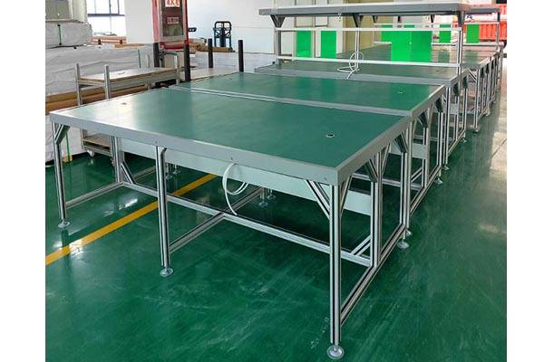
Audit
The eight findings that appear most often
If you are preparing for an audit, these are the items that most often produce a non-conformance in a workstation fit-out. Each is a design or documentation gap rather than a maintenance failure, which is why they recur across sites.
There is a pattern across all eight: the failure is almost never a component that stopped working. It is an assumption that was never tested, or a document that was never written. That is good news, because both are cheap to fix, and it is bad news, because both are easy to overlook when the benches look the part.
FAQ
Frequently asked questions
Build the bench from grounded components
Conductive framing and connectors for an ESD workbench
The grounding path in this specification runs through the frame, the connectors and the surface. These entries are the parts that path is made of, with their finish and material stated.
Specifying ESD workstations for a new line?
We build aluminium profile workbenches with the bonding conductor routed through the T-slot, machined in-house to your ground stud positions, and supplied with the frame finish you specify. Send us your ESD control plan requirements and we will quote to them.
Related reading
Twelve more engineering notes from this blog, picked for this article — plus every category below.
 ApplicationsLean Pipe vs T-Slot Profile: Two Interface Philosophies, Not Two Generations
 ApplicationsHow to Choose the Right 4040 T-Slot Aluminium Profile for Industrial Applications
 ApplicationsAluminium Profiles Across Industries: What Actually Changes From One Sector to the Next
 ApplicationsAluminium Profiles in Industry and Construction: One Material, Two Acceptance Logics
 ApplicationsAluminium Profile Shelving: It Buckles and Tips Before It Bends
 ApplicationsAluminium Greenhouse Profiles: A Snow Load Problem With a Condensation Problem
 ApplicationsAluminium Profile for LED Strips: A Heat Sink First, a Housing Second
 ApplicationsCleanroom and Medical Framing: There Is No Medical-Grade Aluminium Extrusion
 Engineering DesignMoment of Inertia and Section Modulus of T-Slot Profiles
 Materials and EngineeringIndustrial Aluminum Profiles: Alloys, Tempers and How to Select Them
 Engineering Design6063 vs 6061 vs 6082 and T5 vs T6: What Changes in Practice
 Engineering DesignT-Slot Cross-Brand Compatibility: Bosch, Item and Generic
