Aluminium Conduit Profile 40×40 mm Cable Duct T-Slot Enclosure
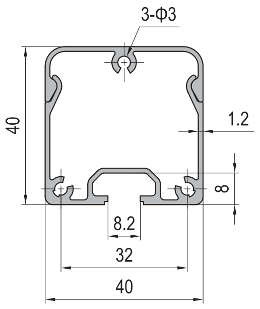
40 x 40 mm aluminium conduit profile in 6063-T5 with a 32 x 8.2 mm internal cavity, a 1.2 mm wall and a weight of about 0.62 kg/m. A cable duct that mounts on the slot of a 40 series profile and closes with a snap or gasketed cover.
| Material | Aluminium |
|---|---|
| Alloy Grade | 6063-T5 |
| Temper | T5 |
| Section Size | 40 x 40 mm |
| Slot | Base has 3 x 3 mm mounting holes for T-slot nut fixing to a 40 series profile |
| Length | 6 m stock, cut to drawing to +/-0.5 mm |
| Tolerance | EN 755-9 / GB/T 6892, wall +/-0.15 mm |
| Surface | Mill finish / clear anodised / black anodised |
| MOQ | 1000 |
| Lead Time | 15-25 days after deposit for mill finish |
| Loading Port | Shanghai / Ningbo |
| Supply Ability | 700 t per month of conduit and duct profiles |
| Payment Terms | T/T 30% deposit + 70% before shipment | L/C at sight |
| Trade Terms | FOB | CIF | EXW |
| Certifications | ISO 9001:2015 | EN 755-9 | RoHS | REACH |
Cable duct · 40 x 40 mm
A 40 x 40 mm aluminium conduit profile is an extruded section with a 40 x 40 mm outside envelope and a 32 x 8.2 mm internal cavity, a wall of about 1.2 mm, and a weight of about 0.62 kg/m in 6063-T5. It is a cable duct that also works as a frame member: it mounts to the slot of a 40 series profile with T-slot nuts, runs alongside the frame, and carries power and signal wiring inside a closed aluminium channel instead of in a plastic trunking strapped to the outside. It is supplied cut to length, with three 3 mm mounting holes on the base, and takes a snap-on or gasketed cover.
The number that decides whether it is the right size is the fill ratio — the percentage of the internal cross-section that the cables occupy. For a closed duct the working limit is normally about 40 %, not 100 %, because cables have to be pulled through without damage, heat has to escape, and the run has to have room for one more cable later. At a 40 % fill the 262 mm2 cavity takes about three Ø6 mm cables or two Ø8 mm cables; at 60 % it takes about five Ø6 mm or three Ø8 mm cables, and it runs hotter. Size the duct on the fill ratio, not on the outer envelope. This section is one of the aluminium conduit profiles we extrude alongside the wider aluminium sections range.
What the 40 x 40 section holds
The internal cavity of this section is about 32 x 8.2 mm, which is a cross-section of roughly 262 mm2. That is a flat, wide channel rather than a round bore, and it suits control and power cable in a frame because the cables lie side by side rather than bunching in a bundle. A flat channel also keeps the cables close to the aluminium wall, which is what helps the duct behave as a heat sink.
The cavity is not the capacity. Capacity is set by the fill ratio, and the fill ratio has to leave room for pulling, for heat and for the next cable. The table below gives the practical cable counts at three fill ratios, and the counts are for cables that run straight through. Bends, entries and transitions reduce them, so a run with more than a couple of direction changes should be sized one step up.
| Fill ratio | Occupied area | Ø6 mm cables | Ø8 mm cables | Ø10 mm cables |
|---|---|---|---|---|
| 40 % (recommended) | about 105 mm2 | about 3 | about 2 | about 1 |
| 50 % | about 131 mm2 | about 4 | about 2 | about 1 |
| 60 % (maximum) | about 157 mm2 | about 5 | about 3 | about 2 |
Fill ratio is a heat limit as well as a space limit
A cable in a closed aluminium duct is not in free air, and the current it can carry depends on how well the heat it produces can get out. Aluminium is a good conductor, so a metal duct behaves far better than a plastic trunking of the same size, but the heat still has to cross the wall and leave the outside face, and a tightly packed duct has less air to move heat from the cable surface to the wall in the first place.
That is why the working limit for a closed duct is normally around 40 % rather than the 100 % that the geometry would allow. At 40 % there is enough free air inside the duct for convection and enough bare wall for radiation, and the cables stay close to their free-air current rating. Push to 60 % and the cables run warmer, which shortens insulation life and, on a power cable, means derating the circuit.
Two rules that cover most cases. Keep the fill under 40 % for any run carrying power, and under 60 % for signal-only cable. Leave the duct slightly oversized rather than exactly sized, because adding one cable to a full duct means re-pulling the whole run.
Fitting the duct into a 40 series frame
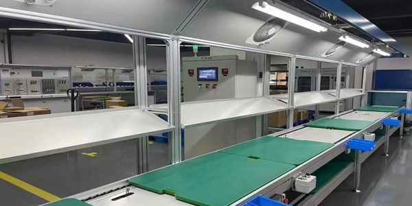
The point of a metal conduit profile rather than plastic trunking is that it belongs to the same system as the frame. It mounts on the slot of a 40 series profile with the same T-slot fastening elements used everywhere else on the strut profile range, so a duct run is designed at the same time as the frame rather than added to it afterwards.
- Decide the run before the frame is built A duct that follows a frame member is invisible and needs no extra support. A duct that crosses a bay needs a bracket, a change of direction or a support, so sketch the run on the frame drawing rather than on site.
- Mount it on the slot with T-slot nuts The three 3 mm holes in the base take M5 or M6 screws into T-slot nuts in the frame slot. Position the holes on the standard slot pitch so the duct can be slid to align with a joint, and leave at least one fixing free until the run is straight.
- Plan the entries and the transitions Cables have to leave the duct at the device they serve. Decide where the entries are and whether they need a grommet, because a cable that leaves through a drilled hole in the wall of a closed duct chafes on the edge unless the hole is bushed.
- Close the ends and the joints Use end caps and joint pieces so the duct reads as one continuous run. On a visible frame the cover line is part of the appearance, so the cover should be fitted in the same direction along the whole run.
- Keep the cover off until the wiring is in Snap covers are made to be opened again for maintenance. Fit the cover after the cables are pulled and tested, and mark the run so the next person knows where the access points are.
Cover, cleaning and protection
The cover decides the protection rating, the cleaning regime and how easy the run is to service, and the three pull against each other. An open channel is easiest to work in and impossible to keep clean in a dusty or wet area; a gasketed cover keeps dust and water out and has to be unscrewed every time a cable is added. Covers, end caps and joint pieces are supplied with the duct as profile accessories, so a run is quoted complete rather than assembled from parts found separately.
| Cover | Protection | Cleaning | Service access | Best for |
|---|---|---|---|---|
| Open channel | None, cables exposed | Poor, collects dust | Immediate | Signal wiring in a clean cabinet |
| Snap-on cover | Dust and light contact only | Good, smooth outside face | Tool-free | General machine and control frames |
| Screw-fixed cover | Dust and splash with a gasket | Very good, wipe down | Screws to remove | Washdown areas and food equipment |
| Gasketed IP-rated cover | IP54 to IP65 with the correct gasket | Excellent, sealed | Screws and gasket to reseat | Outdoor, wet or hygienic installations |
For a hygienic or washdown installation the rule is that the outside of the duct must have no ledges where material can collect. That means a cover that closes flush, fixings that are recessed or hidden, and a gasket in a groove rather than a gasket squeezed onto a flat face. Where the frame is in a clean room or a food area, the duct is usually specified with a smooth cover and a slope on the top face so nothing sits on it.
Alloy and finish
The section is extruded in 6063-T5, which is the right alloy for a duct: it extrudes with a clean surface, anodises evenly, and has more than enough strength for a member that carries cable rather than load. Mill finish is standard and is what most industrial frames use. Clear anodising is chosen where the duct is visible on a machine or a display frame, and black anodising where it has to disappear against a dark frame. Where the duct is inside a washdown enclosure, the anodised surface is also easier to clean than a mill finish and does not leave a mark on a cloth.
Any cutting, drilling or machining is done before the finish is applied, so give the entry positions with the cut list and the holes will be made at the same time. Entries and mounting holes are produced on CNC machining centres, and coloured finishes are run as anodised aluminium profiles in a single batch so the duct matches the frame it sits in.
Frequently asked questions
How many cables fit in a 40 x 40 conduit profile?
The cavity is about 32 x 8.2 mm, or roughly 262 mm2. At the recommended 40 % fill that is about three Ø6 mm or two Ø8 mm cables; at 60 % it is about five Ø6 mm or three Ø8 mm cables, but the run then carries more heat and is harder to service.
Why is the fill limit 40 % and not 100 %?
Because cables have to be pulled through without damage, heat has to escape from the duct, and the run needs spare capacity for one more cable later. A closed duct is also a thermal limit, not only a space limit, so a tightly packed duct forces the cables to be derated.
How does the duct mount to the frame?
Through the three 3 mm holes in the base, with M5 or M6 screws into T-slot nuts in the 40 series profile slot. That means the duct uses the same fixings as the rest of the frame and can be positioned anywhere along a member.
Can I get an IP-rated version?
Yes, with a gasketed cover and the correct gasket the duct reaches IP54 to IP65. For washdown or hygienic areas, specify a flush cover, recessed fixings and a gasket in a groove rather than on a flat face.
What alloy and finish do you supply?
6063-T5 as standard, in mill finish, clear anodised or black anodised. Cutting, drilling and machining are done before the finish, so send the entry positions with the cut list.
Send the cable schedule, not only the duct size
Tell us how many cables and what sizes they are, and we will confirm the fill ratio and whether 40 x 40 is the right duct before you commit. Send the frame drawing, the entry positions and the mounting hole pattern, and we will quote the extrusion, the cutting, the drilling, the gasket groove and the finish as one package with FOB pricing, supplied with covers and end caps bagged by assembly.
Request a QuoteRelated Products
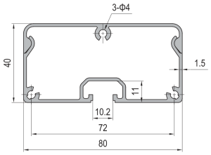 Aluminium Conduit Profile 40×80 mm Large Cable Duct Enclosure
40 x 80 mm aluminium conduit profile in 6063-T5 with a 66 x 11…
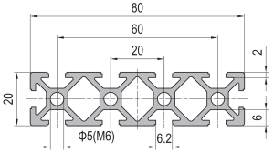 PG20 80×20 mm Ten Slot Aluminium Strut Profile Wide Flat Beam for Cable Tray and Panel Support
80 x 20 mm ten slot PG20 aluminium strut profile in 6063-T5 with a…
 PG20 40×40 mm Eight Slot Aluminium Strut Profile 20 mm Pitch T-Slot Extrusion for Dense Fixtures
40 x 40 mm eight slot PG20 aluminium strut profile in 6063-T5 with two…
 PG30 30×30 mm Two Slot Type A Aluminium Strut Profile Closed Face T-Slot Extrusion
30 x 30 mm Type A two slot PG30 aluminium strut profile in 6063-T5…
 PG30 30×30 mm Two Slot Type B Aluminium Strut Profile Symmetric T-Slot Extrusion for Corner Posts
30 x 30 mm Type B two slot PG30 aluminium strut profile in 6063-T5…
 PG30 30×30 mm Three Slot Aluminium Strut Profile Light Frame Column
30 x 30 mm aluminium strut profile with three 8.2 mm T-slots and one…
 PG30 30×30 mm R90 Two Slot Aluminium Strut Profile Rounded Corner Rail
30 x 30 mm quarter round aluminium profile with one 8.2 mm T-slot on…
 PG30 60×30 mm Six Slot Aluminium Strut Profile Rectangular T-Slot Extrusion for Cabinet Uprights
60 x 30 mm six slot PG30 rectangular aluminium strut profile in 6063-T5 with…
