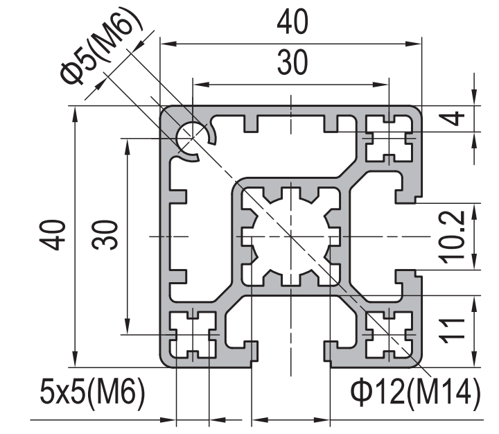
PG40 40 x 40 mm Two Slot Type A Aluminium Strut Profile Guide Rail
40 x 40 mm Type A two slot asymmetric PG40 aluminium strut profile in 6063-T5 with 10.2 mm grooves on adjacent faces. For cantilever arms, single sided panels, guide rails and sealing faces.
| Material | Aluminium |
|---|---|
| Alloy Grade | 6063-T5 |
| Temper | T5 |
| Section Size | 40 x 40 mm |
| Slot | 2 x 10.2 mm groove, 8 mm mouth, adjacent faces, 30 mm pitch, M8 |
| Length | 6 m stock, cut to drawing to +/-0.5 mm |
| Tolerance | EN 755-9 / GB/T 6892, wall +/-0.15 mm |
| Surface | Mill finish / clear anodised / black anodised |
| MOQ | 500 m |
| Lead Time | Typically 15 to 25 days after deposit for mill finish |
| Loading Port | Shanghai, Ningbo, Qingdao |
| Supply Ability | Extrusion, cutting, machining and anodising in house |
| Payment Terms | T/T 30 per cent deposit, balance against copy of bill of lading; L/C at sight for larger orders |
| Trade Terms | FOB, CIF, CFR, EXW |
| Certifications | ISO 9001:2015, EN 755-9, RoHS and REACH declarations |
01What is the 40 x 40 mm two slot Type A profile?
How is Type A different from a normal four slot 40 x 40?
The two grooves are on adjacent faces rather than on all four. That leaves two closed faces, and because the grooves are adjacent those two closed faces meet at a single corner. You end up with an L shaped run of solid, unbroken surface wrapping one corner of the section.
Why would you want fewer slots?
Because a slot is a hole in your datum. Every groove interrupts the surface, and a groove cannot be machined, sealed or run against. When the section has to act as a guide rail, a sealing face or a machined reference, the faces without grooves are the ones doing the work, and you want as many of them as possible in one piece.
Is the section weaker for having two slots?
In bending, marginally stiffer if anything, because there is slightly more material left in the walls. At about 1.95 kg/m it is in the same weight class as a four slot 40 x 40. The trade is not strength, it is where you are allowed to fix things.
02Section data
| Item | Value | Note |
|---|---|---|
| Envelope | 40 x 40 mm | square, sharp corners |
| Slots | 2 | 10.2 mm groove, 8 mm mouth |
| Slot layout | adjacent faces | not opposite, not all four |
| Closed faces | 2 | meeting at one corner, continuous |
| Slot pitch | 30 mm | between centres |
| Fastener | M8 | standard 40 series slot nut |
| Centre bore | 12 mm, tapped M14 | for end connections |
| Wall | 2.2 mm nominal | varies by face |
| Weight | approx. 1.95 kg/m | a 6 m bar is about 11.7 kg |
| Alloy | 6063-T5 | EN AW-6063 |
| Standard | EN 755-9 / GB/T 6892 | wall tolerance +/-0.15 mm |
| Length | 6 m stock | cut to drawing to +/-0.5 mm |
The centre bore is 12 mm tapped M14, which is the detail most buyers miss on this section. It lets you pull a heavy end connection straight through the middle of the member instead of hanging it off the slot lips. If your end load is significant, that is the fixing to specify.
03The closed corner is the point of the section
Think about what a groove does to a surface. It removes material, it creates two lips that flex, and it leaves a step that a sliding carriage will catch on. A sliding shoe, a linear rail, a brush seal or a magnetic strip all need a continuous flat face, and none of them can be fitted across a groove.
On a four slot section, every face has a groove down the middle, so there is no continuous flat face wider than the gap between the groove and the corner. On the Type A section, two faces are clean and they meet at a corner, so the usable flat runs around the corner. That is what makes it a guide rail section rather than a general framing section.
The same logic applies to machining. If you need to mill a slot, drill a pattern of holes on a precise pitch, or bond a scale or a sensor strip to the face, you want the face to be solid under the cutter. Machining across a groove breaks the cutter and leaves a burr that is almost impossible to remove from inside the groove.
And it applies to sealing. A gasket, a brush strip or a panel seal needs a flat land to compress against. A groove underneath it is a leak path.
| Job the face has to do | Four slot 40 x 40 | Two slot Type A |
|---|---|---|
| Carry a sliding carriage | no, the groove interrupts it | yes, continuous |
| Take a linear rail | needs an adapter plate | mounts directly |
| Carry a brush or gasket seal | leak path under the seal | yes, flat land |
| Be milled or drilled on a pitch | breaks out into the groove | yes, solid |
| Bond a scale or sensor strip | no continuous land | yes, full length |
| Bolt an accessory anywhere | yes, on all four faces | only on two faces |
| Carry panels on all sides | yes | no |
The last two rows are the honest cost. You give up the ability to fix to all four faces. If the finished assembly genuinely needs something bolted to every face, this is the wrong section and the four slot one is right. The Type A is for the case where two faces fix and two faces work.
04Deciding between Type A, Type B and the four slot section
Type A, two slots on adjacent faces
- Two faces must be continuous: a carriage, a rail, a seal or a scale
- You need a machined datum on the section itself
- The member is a guide rail, a cantilever arm or a fence rail
- Panels go on one side only, or on two adjacent sides
- The end connection is heavy and uses the M14 centre bore
Four slot, all faces open
- Accessories bolt on every face
- The member is a general frame member with no special faces
- The frame is built from corner brackets throughout
- Nothing slides against the section and nothing is machined
- You want one section reference for the whole frame
Type B, the other two slot variant, puts the two grooves on opposite faces. That gives you two closed faces that do not meet, which is right when you need two separate sealed lands facing in different directions rather than one continuous run around a corner.
A way to settle it quickly: sketch the finished member and shade the faces that something has to slide on, seal against or be machined into. If those shaded faces are adjacent, Type A. If they are opposite, Type B. If there are none, four slot.
05Failure modes to design out
| What goes wrong | Why it happens | Design it out by |
|---|---|---|
| Carriage catches on a groove | the wrong section was used, or the rail was mounted over a groove | confirm the closed faces are the ones the carriage runs on before ordering |
| Cantilever arm creeps downwards | an arm loaded at the end works the slot lips, not the section | support the arm, or use the M14 centre bore for a through connection |
| Machined hole breaks into a groove | the hole pattern was laid out without accounting for the groove positions | dimension the hole pattern from the closed corner, not from the section edge |
| Seal leaks along the groove | a gasket was laid across the open side of the section | fit the seal on a closed face, or fill the groove with a cover strip first |
| M14 centre bore thread strips | the tapped depth is shallow and the bolt was tightened to the steel figure | state the engagement length required and torque to the aluminium figure |
06What to check before you order
Procurement checklist for the 40 x 40 mm two slot Type A section
- Confirm Type A against Type B. A has the two grooves on adjacent faces, B on opposite faces. They are not interchangeable.
- Confirm which faces the grooves are on in the finished assembly, and that the closed corner is where the carriage, rail or seal goes.
- Confirm the centre bore requirement: whether the 12 mm bore needs tapping M14 and to what depth.
- Confirm the end machining: square cut, tapped end, or drilled for a bracket.
- Confirm the accessory list in the 40 series: M8 slot nuts, cover strips for the two grooves, and end caps.
- Confirm the finish: mill for a member that will be clad, anodised where the closed faces are visible.
- Confirm the quantity in metres and the offcut allowance.
07Terms used on this page
- Type A and Type B
- The two two-slot variants of the 40 x 40 section. A puts the grooves on adjacent faces, B on opposite faces.
- Closed face
- A face with no groove, left as solid wall. It is the face you machine, seal against or run a carriage on.
- Datum
- A surface used as the reference for measuring or machining. Grooves destroy datums, which is why closed faces are specified.
- Centre bore
- The round hole running down the middle of the section, here 12 mm and tapped M14 for end connections.
- Carriage
- A sliding shoe or plate that runs along the outside of a section and needs a continuous flat face.
- Cover strip
- A snap-in profile that fills an unused groove, giving a smooth face and keeping debris out.
08Questions buyers ask
What is the difference between Type A and Type B?
Type A has the two grooves on adjacent faces, so the two closed faces meet at one corner and form a continuous flat run. Type B has them on opposite faces, giving two separate closed faces.
Can a linear rail be mounted directly to it?
Yes, that is what the closed faces are for. Mount the rail on a closed face and use the two grooves on the adjacent faces for the brackets that hold the assembly.
Is it as strong as the four slot section?
In bending it is in the same class and marginally stiffer because there is more wall left. The difference is in where you can fix, not in how much it carries.
What is the centre bore for?
It is 12 mm and tapped M14, which takes a heavy end connection straight through the middle of the member instead of loading the slot lips.
What is the weight per metre?
Approximately 1.95 kg/m, so a 6 m stock length is about 11.7 kg.
Can the unused grooves be covered?
Yes, 40 series cover strips snap into the groove and give a smooth face as well as keeping swarf and dust out.
What we need to quote this section
- The variant: Type A or Type B, stated explicitly.
- The cut list with lengths and which end is machined.
- The centre bore requirement: plain, or tapped M14 and to what depth.
- Any milling or hole pattern on the closed faces, dimensioned from the closed corner.
- The accessory list: M8 slot nuts, cover strips, end caps.
- The finish and the quantity in metres.
Quotations are broken out into extrusion, cutting, end machining, finish and hardware, so you can see which step is driving the cost. Browse the full aluminium profile catalogue and the 40 series aluminium profiles range for related sections.
Using a 40 x 40 section as a guide rail or sealing face?
Send the variant, the cut list and the machining requirement. We quote extrusion, machining, finish and the 40 series hardware as separate lines.
Request a quotationRelated Products
 PG40 40 x 40 mm Two Slot Type B Aluminium Strut Profile Opposite Rail
40 x 40 mm Type B two-slot aluminium strut profile with two 10.2 mm…
 PG40 40 x 40 mm Four Slot Heavy Aluminium Strut Profile Standard Frame
40 x 40 mm heavy-wall four-slot aluminium strut profile with 10.2 mm grooves, 8…
 PG40 40×40 mm Four Slot Light Wall Aluminium Strut Profile Cost Optimised T-Slot Extrusion
40 x 40 mm four slot light wall PG40 aluminium strut profile in 6063-T5…
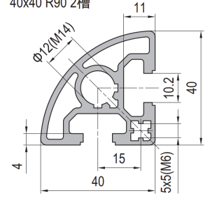 PG40 40×40 mm R90 Quarter Round Aluminium Strut Profile Radius Corner Guard Frame Extrusion
40 x 40 mm R90 quarter round PG40 aluminium strut profile in 6063-T5 with…
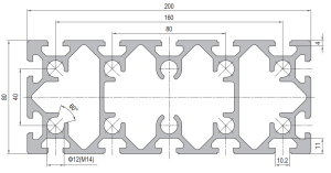 PG40 200 x 80 mm Fourteen Slot Aluminium Strut Profile Large Section Beam
A 200 x 80 mm fourteen slot PG40 aluminium strut profile at about 7.80…
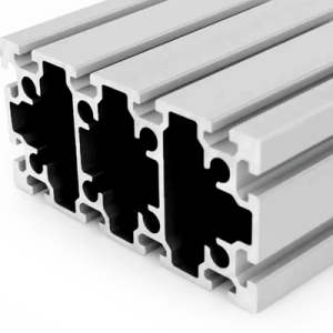 PG45 180 x 90 mm Twelve Slot Aluminium Strut Profile Heavy Duty Column
A 180 x 90 mm twelve slot PG45 aluminium strut profile at about 9.50…
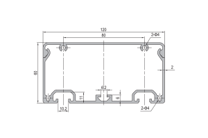 Aluminium Conduit Profile 120×60 mm Cable Duct Extrusion 2 mm Wall for Machine Wiring
120 x 60 mm aluminium conduit profile duct in 6063-T5 with a 2 mm…
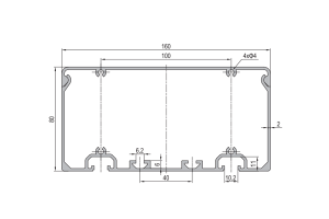 Aluminium Conduit Profile 160×80 mm Cable Duct Extrusion with Two Sided Mounting for Machine Frames
160 x 80 mm aluminium conduit profile duct in 6063-T5 with a 2 mm…
