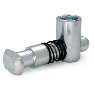
Standard Connector Model C Aluminium Profile Corner Joint 90 Degree 30 40 mm Series
Model C standard connector for a 90 degree corner in aluminium profile with both members square cut. Internal joint with a clean outside corner, for 30 and 40 series sections.
| Material | Steel |
|---|---|
| Alloy Grade | Carbon steel |
| Temper | custom |
| Section Size | 30 series / 40 series |
| Slot | Matches the groove of the receiving section |
| Length | By series, to drawing |
| Tolerance | End face square to the axis, burr free |
| Surface | Zinc plated |
| MOQ | 2000 |
| Lead Time | 18-28 days after deposit |
| Loading Port | Shanghai / Ningbo |
| Supply Ability | 1,000,000 pieces per month |
| Payment Terms | T/T 30% deposit + 70% before shipment | L/C at sight |
| Trade Terms | FOB | CIF | EXW |
| Certifications | ISO 9001:2015 | RoHS | REACH |
Connecting · Standard connector
A standard connector, Model C, joins two profiles at 90 degrees where both ends are cut square. The connector is fitted into the end face of the incoming member and expands into the groove of the receiving member, pulling the two faces together. It is the default way to make a right-angle corner on an aluminium profile frame.
It is the default because it asks the least of the cutting operation. Both members are cut to length and square, which is one setting on the saw and one dimension to hold. There is no angle to set, no pair of angles that have to agree, and no thin arris left on the end face. That combination is why most frames are built this way and why a square-cut corner is the first thing to consider before any other joint type.
The case for a square-cut corner
Joint choice on a profile frame usually starts with appearance and works backwards to method. That is the wrong order. Start with the cut, because the cut decides how much accuracy the joint can hold and how much material ends up as scrap.
A square-cut corner needs one saw setting and one length dimension per member. A mitred corner needs an angle setting that is accurate to half a degree, held twice, and it turns the end of every member into a wedge with a thin edge. Given that the two look identical from any distance where the frame is used rather than examined, the square cut is the sensible default and the mitre is the exception you choose deliberately.
| Square cut, Model C | Mitred, Model P | |
|---|---|---|
| Saw settings per member | One, length only | Two, length and angle |
| Angle accuracy needed | None | Within 0.5 degrees |
| End face condition | Full wall thickness | Tapered to a knife edge |
| Scrap on a wrong cut | Re-cut one member | Re-cut both members |
| Assembly adjustment | Possible before final tightening | Almost none |
| Where it belongs | Most frames | Frames that are looked at |
What the connector does in the joint
The connector is a bolt with a spring and an expanding sleeve. It is pushed into the end face of the incoming member, where the sleeve sits inside the tapped or drilled hole, and the sleeve enters the groove of the receiving member as the member is offered up from the side. Turning the bolt expands the sleeve against the inside of the groove and pulls the two end faces together.
Two things carry the load. The friction between the expanded sleeve and the groove resists the joint being pulled apart, and the contact between the two square-cut faces carries compression and stops the joint closing further. Because the faces are square and full thickness, they can take that contact load without deforming, which is the practical advantage a square cut has over a mitre.
Where the Model C connector stops and a bracket starts
Both a Model C connector and an angle bracket make a 90 degree corner, and the choice between them is not about strength. It is about whether the joint needs to be adjustable, whether the outside of the frame has to stay clean, and whether the frame will come apart again.
The connector is internal, so the outside of the corner stays clean and there is nothing to catch on. It also needs the end face to be drilled and tapped before assembly, and once tightened it is not designed to be adjusted. A bracket is external, so it shows, but it needs no end-face preparation, it can be slackened and moved, and it can be added to a frame that was already built.
| Requirement | Model C connector | Angle bracket |
|---|---|---|
| Outside of the frame must stay clean | Yes | No, bracket shows |
| Joint has to be adjustable after assembly | No | Yes, slots allow movement |
| End face can be drilled and tapped | Required | Not required |
| Frame will be dismantled repeatedly | Not recommended | Yes |
| Corner needs extra stiffness | Only what the connector gives | Add a gusset bracket |
| Fitting time per corner | Low once faces are prepared | Low, no preparation |
Getting the end face right
- Cut square and deburr both faces The two faces that will meet have to be square to the axis and free of burr. Burr on an end face holds the joint open by its own thickness, and on an anodised section it also breaks through the coating at the corner.
- Drill and tap the incoming member on a jig The hole has to be on the centre line of the groove it will expand against. Mark and drill by hand and the connector will bear on one flank of the groove instead of the full width, which halves the holding force.
- Check the hole depth before fitting The sleeve needs its full length plus about 2 mm of clearance. A hole that is too shallow lets the connector bottom out before the end faces meet, and the joint then looks tight while the faces are still apart.
- Assemble and tighten to the specified torque Offer the member in from the side, engage the sleeve in the groove and tighten to the figure for the section. Stop there. Past that torque the sleeve deforms the groove and the joint gets looser rather than tighter.
Model C or Model P? If both members can be cut square, use Model C. It is faster, wastes less, tolerates ordinary cutting accuracy and leaves a full-thickness end face. Choose Model P only when the corner is on show and a bracket or a square-cut transition would be visible.
Frequently asked questions
What is a Model C standard connector?
A connector for a 90 degree corner in aluminium profile where both members are cut square. It fits into the end face of one member and expands into the groove of the other, giving an internal joint with a clean outside corner.
How is it different from a miter connector?
Only in the cut it expects. A miter connector needs both members cut at 45 degrees and joined on a mitred face. A Model C connector needs both members square cut. The Model C is easier to make, wastes less material and holds accuracy better.
Do I need to drill and tap the end face?
Yes. The connector sits in a hole in the end face of the incoming member, so that hole has to be drilled and tapped before assembly and it has to be on the groove centre line. It is best done on a jig rather than marked and drilled by hand.
Can I adjust the joint after assembly?
The joint can be loosened and re-tightened, but the position is set by the end faces meeting, so there is no adjustment range in the way a slotted bracket gives. If the joint needs to move, use a bracket instead.
Which sections does it suit?
Standard 30 series and 40 series sections. Tell us the section you are using and the joint you are making and we will confirm the correct connector and the end-face hole specification.
Tell us the section and the corner you are making
Send the profile you are using and confirm whether the ends are square cut. We will recommend the correct Model C connector, quote the bulk price and supply samples with the hole specification.
Request a QuoteRelated Products
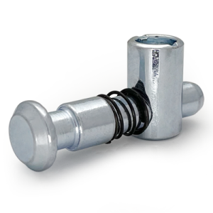 Universal Connector Aluminium Profile Adjustable Angle Joint Fastener M8 30 40 mm
Universal connector for aluminium profile with an angle set during assembly. Suits diagonal braces,…
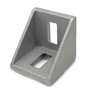 Die Cast Bracket for 20 to 50 mm Series Aluminium Profiles Corner
Die cast zinc alloy corner bracket for 20, 30, 40, 45 and 50 series…
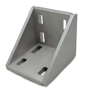 Heavy Duty Die Cast Corner Bracket for Aluminium Profile 60 80 90 100 mm Series
Heavy duty die cast corner bracket for large aluminium profile frames in 60, 80,…
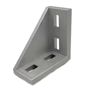 Rectangular Die Cast Corner Bracket Aluminium Profile 30×60 40×80 45×90 50×100 mm
Rectangular die cast corner bracket with unequal legs for aluminium profile frames built from…
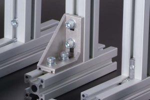 Aluminium Extrusion Connector System for 20×20 to 100×100 mm T-Slot Frames
A complete aluminium extrusion connector system covering visible brackets, hidden inner brackets, cubic corner…
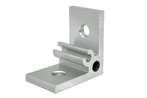 Aluminium Angle Profile Bracket 35x35x4 mm M6 Corner Brace for 20 and 30 Series Profiles
A 35 x 35 x 4 mm aluminium angle profile bracket for 20 and…
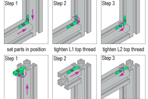 Aluminium Inner Bracket with Top Thread M5 M6 M8 for 20 to 40 mm T-Slot Profiles
A hidden inner bracket with top thread for aluminium T-slot profiles, supplied in M5…
 Aluminium Cubic Connector 2020 20×20 mm Three-Way Corner Joint with ABS Cap
A 20 x 20 x 20 mm three-way cubic corner connector for 20 series…
