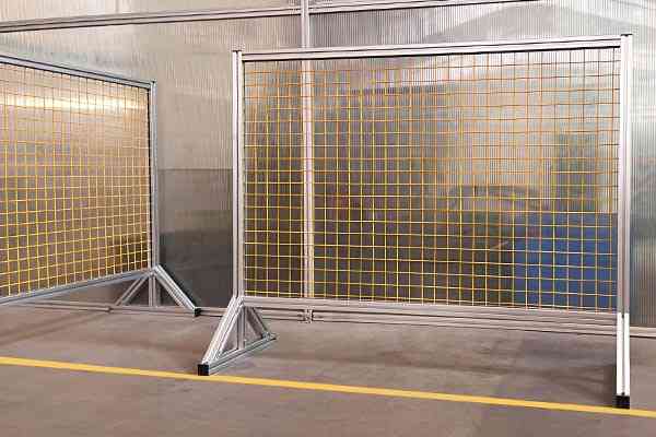
Quick answer
Two calculations cover most guard door problems
For a sagging door: multiply the door weight by the horizontal distance from the hinge axis to the centre of gravity. That is the hinge moment, in newton-metres. Divide it by the number of hinges, then apply a safety factor of at least 2 for a guard that operators lean on. A 20 kg door with its centre of gravity 450 mm from the hinge needs about 88 N·m per hinge pair, or 88 N·m per hinge at factor 2.
For a slamming door: kinetic energy is half the mass times the closing speed squared. A 25 kg door closing at 0.5 m/s carries 3.1 joules. That is trivial to absorb over a 40 mm buffer stroke and brutal to absorb over 2 mm of metal-on-metal contact — the difference is a factor of twenty in peak force.
And the compatibility trap: European 8.2 mm hardware geometry fits 40-series profiles with an 8 mm slot, but “8 series” hardware from other systems can use 6.6 mm holes and M6 bolts. The plate looks the same in a photo and has half the capacity.
Sag
Sizing hinges: the moment calculation that predicts door sag
A hinge does not fail by snapping. It fails by letting the door rotate down at the free edge, a few tenths of a millimetre per week, until the door catches the frame and the latch stops lining up. That is a moment problem, and it is calculable before you order anything.
M = W × g × dM is the hinge moment in N·m. W is the door mass in kg. g is 9.81 m/s². d is the horizontal distance from the hinge axis to the door’s centre of gravity, in metres — for a uniform door, that is half the door width.Two things about that formula cause almost all the surprises. First, d is measured from the hinge axis, not from the frame. If the hinge sits on a spacer that moves the door 30 mm out, d grows by 30 mm and the moment grows with it. Second, the panel counts. A 3 mm polycarbonate panel adds about 3.6 kg per square metre; a 4 mm steel mesh infill adds far more. Doors are usually heavier than the frame that carries them.
Worked example: a 1800 × 900 mm guard door on 4040 profile
Frame perimeter 5.4 m of 4040 profile at roughly 1.7 kg per metre is 9.2 kg. A 3 mm polycarbonate panel of 1.62 m² adds 5.8 kg. Add hinges, a handle, a latch and a window frame and the door lands at about 20 kg.
M = 20 kg × 9.81 × 0.45 m = 88 N·mWith two hinges sharing the load evenly, each hinge carries 44 N·m. With a safety factor of 2 — appropriate for a guard an operator may lean on or bump with a pallet truck — each hinge must be rated for at least 88 N·m.Why the top hinge takes more
Two hinges do not share the load evenly once the door sags. As the door drops at the free edge, the geometry shifts load onto the upper hinge, which is also the hinge that must resist the vertical pull-out. This is why a door rated for two hinges at 88 N·m each still sags: the real split can be 70/30, not 50/50. Either uprate the hinges by one size or use three.
Slam
Sizing buffers and end stops: the energy calculation
A sliding guard door on a machine frame typically weighs 15 to 40 kg and closes at 0.3 to 0.8 m/s depending on how hard it is pushed. That energy has to go somewhere, and the only choice you get is how gradually.
E = ½ × m × v²E is kinetic energy in joules, m is the moving mass in kg, v is the closing speed in m/s. Average force during deceleration is then F = E / s, where s is the deceleration distance in metres.Worked example: a 25 kg sliding guard closing at 0.5 m/s
The kinetic energy is 0.5 × 25 × 0.5² = 3.13 J. That sounds small, and it is — the problem is entirely the stopping distance.
| How it stops | Stopping distance | Average force | What the operator hears |
|---|---|---|---|
| Bare profile against end stop | ~2 mm | 1,560 N | A bang, every cycle, all shift |
| Rubber bumper | ~8 mm | 390 N | A thud that gets louder as the rubber hardens |
| Spring end stop | ~20 mm | 156 N | A clack, with some rebound |
| Hydraulic buffer, 40 mm stroke | 40 mm | 78 N | Almost nothing, and no rebound |
Read the first and last rows together. The buffer reduces peak force by a factor of twenty, not because it is stronger, but because it buys twenty times the distance to stop in. It also removes the rebound, which is what actually damages sliding doors: a door that bounces back off a hard stop re-hits it, and the second impact often lands on a different part of the track.
The end stop still has to be rated
A buffer absorbs energy; the end stop behind it carries the residual static load. Size the end stop for at least the peak buffer force — around 150 N here, so a 500 N rating gives sensible margin — and mount it so the load goes into the profile web rather than through the slot flange. An end stop bolted only through a single T-nut will tear the flange before it bends.
Specification
What to put in the specification for guard hinges
Guard hardware is bought on a photo and a price far too often. These are the seven lines that make the second order identical to the first, and they are the same lines that let you compare two quotes honestly.
One more line worth adding, because it is free: ask for the hinge to be supplied with its fasteners. Mixing a hinge from one supplier with nuts from another is how a correctly rated hinge ends up in an under-rated joint, since the T-nut is normally the weakest element in the connection.
Compatibility
Fitting hardware to 40-series profiles: the geometry traps
The phrase “fits 40 series” is not a specification. Three different geometries are sold under it, and they are not interchangeable.
| Geometry | Hole size | Fastener | Where it goes wrong |
|---|---|---|---|
| European 8.2 mm geometry | 8.2 mm | M8 | The standard for 40-series work. Fits an 8 mm slot mouth with a 30 mm pitch. This is the geometry to specify unless you have a reason not to |
| 8 series with 6.6 mm holes | 6.6 mm | M6 | Looks identical in a product photo. Same outline, roughly half the moment capacity, and it will not accept the M8 bolts you already stock |
| 30-series geometry | 6.6 mm | M6 | Fits a 6 mm or 8 mm slot depending on the profile. The plate is smaller than it needs to be for a 40-series face, so it sits off-centre |
How to check in thirty seconds
Measure the mounting hole with callipers before anything else. 8.2 mm means M8 and 40-series capacity. 6.6 mm means M6, whatever the listing says. Then check the pitch against the profile’s 30 mm slot spacing — a plate with 40 mm pitch on a 30 mm pitch profile will only ever bolt through one hole per face, and a hinge held by one bolt per face is a hinge that will sag.
The profiles and hardware referenced here are grouped on the 40 series aluminium profiles page, with fasteners under fastening elements and guarding applications under applications. If the guard has to meet a specific standard, our article on ISO 14120 machine guard design walks through the frame side of the same problem.
Frequently asked questions
How do I calculate the right hinge for a machine guard door?
Multiply the door mass by 9.81 and by the horizontal distance from the hinge axis to the door’s centre of gravity. That gives the hinge moment in N·m. Divide by the number of hinges, then multiply by a safety factor of at least 2, and 3 where a person or a pallet truck can lean on the door. A 20 kg door with a 450 mm centre of gravity distance needs about 88 N·m per hinge at factor 2.
How many hinges does a guard door need?
Two is the practical minimum for any door, and three for doors taller than about 1,500 mm or heavier than about 35 kg. Two hinges do not share load evenly once the door starts to sag — the split can be 70/30 in favour of the upper hinge, which is also the one resisting vertical pull-out. If you are near the limit with two hinges, adding a third is cheaper than uprating the pair.
Do I really need a buffer on a sliding guard door, or is an end stop enough?
A plain end stop works, but it turns the door’s kinetic energy into a hard impact. A 25 kg door closing at 0.5 m/s carries 3.1 J; stopping that in 2 mm of metal contact means about 1,560 N of peak force, every cycle. A hydraulic buffer with a 40 mm stroke absorbs the same energy at about 78 N and eliminates rebound. If the door cycles more than a few times a shift, the buffer pays for itself in noise, wear and latch alignment.
How do I size a sliding door buffer?
Work out the kinetic energy first: half the mass times the closing speed squared. Then divide by the stroke length you can physically fit. A 25 kg door at 0.5 m/s is 3.1 J; a 40 mm stroke means an average force of about 78 N and a peak of roughly twice that. Size the buffer for the energy, size the end stop behind it for the peak force, and mount both so the load goes into the profile web rather than the slot flange.
What does “8.2 mm European geometry” mean for aluminium profiles?
It refers to the mounting hole diameter and bolt pattern on the hardware plate: 8.2 mm holes for M8 bolts, matching the 8 mm slot mouth and 30 mm slot spacing of 40-series profiles. It is the common standard for European automation hardware. The trap is that some suppliers sell hardware with 6.6 mm holes under the same “fits 40 series” description, which takes M6 bolts and roughly half the moment capacity.
How many cycles should guard hardware be rated for?
Estimate the daily cycles first: a guard opened 100 times a day is about 25,000 cycles a year. Specify a minimum of 100,000 cycles for hinges and buffers on a production machine, and ask for the test method rather than a datasheet figure. Hinges on high-cycle automated guarding should be specified higher again, and the pin and bush material becomes the deciding factor rather than the plate.
Send us the door weight and we will size the hardware
Give us the door dimensions, panel material and cycle rate. We will come back with the hinge moment, the buffer energy, and a hardware list that matches the 40-series profiles you are already using.
Related reading
Twelve more engineering notes from this blog, picked for this article — plus every category below.
 Engineering DesignWhat Is a 2020 Aluminium Profile? (Weight, Slot and Load)
 Engineering Design4080 vs 4545 Aluminium Profile: Which for Your Frame
 Engineering DesignAluminium Profile Basics: What the Series Numbers and Slot Codes Mean
 Engineering DesignAluminium Profile Sizes: The Four Slot Dimensions That Decide Compatibility
 Engineering DesignCross-Brand T-Slot Compatibility: Interchangeability Is a Hardware Question
 Engineering DesignHow to Choose the Right T-Slot Aluminium Profile for Your Project
 Engineering DesignHow to Request a Quote for Custom Aluminium Extrusion (RFQ Checklist)
 ApplicationsAluminium Workbench Fit-Out: When the Accessories and the Joints Compete for the Same Slot
 Sourcing and ProcurementAluminium Profile Quote: What Changes the Number by Quantity
 Quality and InspectionEuropean Anodised Aluminium Specification: What Should a Purchase Order Contain?
 Materials and EngineeringAnodised vs Powder Coated Aluminium Profiles: A Specification Guide for European Buyers
 ApplicationsAluminium Profile Fish Tank Frames: Glass Load, Salt Water, and the Alloy Question
