Aluminium Workbench Fit-Out: When the Accessories and the Joints Compete for the Same Slot
The top and the frame are two separate design problems, and we have written about them separately. The layer that decides whether a bench actually works is the one above that: what hangs off it, and whether there is any slot left to hang it from.
Short answer
A workbench has three layers: the top, the frame, and the accessory layer. The third one is where most benches disappoint, and it fails for a reason that is easy to predict and rarely checked. Every joint consumes slot length, and every accessory needs slot length, and on a modest bench the two run out at the same time. Add the two structural consequences of fit-out, which are that a height-adjustable bench is a different structure when raised, and that a bench on castors is free to move rather than rigid, and you have the three things worth deciding before the frame is drawn. Where the bench also has an electrical or static-control duty, a fourth item joins them: an anodised frame does not conduct through its joints, so continuity has to be designed rather than assumed.
Three layers, and the third one is where it goes wrong
The first layer is the work surface: its material, its thickness, its flatness and how it is attached. The second is the frame: the section, the span and the joints that carry the top and whatever sits on it. Both of these get designed, quoted and checked.
The third layer is the accessory layer: everything that hangs off the frame to make the bench usable. Pegboards, tool rails, monitor arms, lighting arms, power and air outlets, bin rails, drawer units, cable management, clamps, vices, and the mounting plates that hold all of them.
This layer is usually added late, by a different person, after the frame drawing is fixed. It is also the layer that determines whether the bench works, because a bench without usable tool storage is a table. And it is the layer that interacts badly with the frame, because it competes for exactly the same resource the frame’s own joints are using.
Slot contention: the arithmetic nobody does
A slot is a finite resource. A one metre upright has one metre of slot on each face, and both the joints and the accessories want it.
Every concealed joint consumes slot. A corner connection that uses a concealed connector occupies a length of slot roughly equal to the connector’s body, and that length is then unavailable. A frame with joints at both ends of a rail and a bracket in the middle has already spent a significant part of the rail’s slot before a single accessory is fitted.
The check is simple and it takes ten minutes. For each member, list the joints it carries and the accessories it must support, estimate the slot length each one occupies, add them, and compare with the member’s length. On a bench of a metre or less the answer is frequently that the list does not fit, and the fix is cheaper at the drawing stage than after delivery.
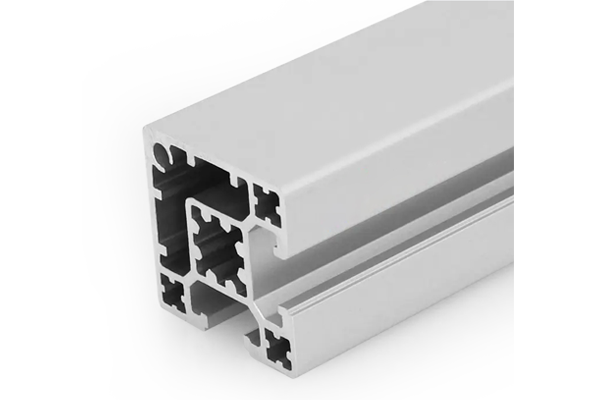
There are four ways out, and they are worth knowing before the design is fixed. Move the joint to a different face of the profile. Use a bracket that bears on the outside of the section instead of inside the slot. Use the tapped centre bore for feet and end attachments, which consumes no slot at all. Or step up a section size, which increases the available slot length per face as well as the stiffness.
A reserve worth keeping
Leave roughly a quarter of each member’s slot unused. Benches grow: a bin rail, an extra clamp, a new tool holder. A frame with no spare slot forces the next addition to be a rebuild.
The accessory list is a load case
Accessories are usually specified by function and by appearance, and rarely by the load and the moment they impose. That is a mistake, because several of them apply a load at the end of a lever, which is a much harder case than the same weight sitting on the frame.
| Accessory | Load character | What it demands of the frame |
|---|---|---|
| Pegboard or tool panel | Distributed, plus point loads from tools | Slot length along two uprights; panel stiffness of its own |
| Monitor or lighting arm | Point load at the end of a lever | A moment at the mounting point, and a section that will not twist |
| Power strip or air outlet | Light, but permanent | Slot length, plus a cable route that does not foul the tools |
| Bin rail or shelf | Distributed, often overloaded in practice | Two uprights and a bracket that bears on the section, not the lip |
| Drawer unit or cabinet | Concentrated, and heavier than quoted | A real bracket load, and access for the fixings |
| Vice or press | High point load with impact and a long lever | Direct load into the top and the frame, not through a slot |
| Cable chain or festoon | Repeated dynamic load | A fatigue consideration, not just a static one |
The pattern is that anything on an arm, and anything that a person pulls or leans on, produces a moment rather than a weight. Moments are what deform slot lips and twist frames, and they are the reason the frame has to be checked against the accessory list rather than against the top load alone.
Vices, presses and heavy drawer units are the cases that most often deserve to be taken out of the slot entirely. A vice bolted through the top and into a frame member, or onto a dedicated plate, is a different proposition from a vice on a bracket in a slot.
A raised bench is a different structure
Height adjustment changes the geometry, and the change is not favourable.
A bench at its lowest setting has short columns and a low centre of gravity. The same bench at its highest setting has tall columns, and lateral stiffness falls quickly with column length. If the bench is also narrow, the combination of a tall column and a light base produces sway: the bench moves when the operator leans on it or when a machine on it starts up.
Two practical consequences. First, the design case for a height-adjustable bench is the fully raised position, not the working position, and the stability check should be done there. Second, the raised position is where the locking mechanism is doing the most work, so the quality of the lock matters more than the quality of the lift. A bench that rises smoothly and locks poorly is worse than one that rises slowly and locks firmly.
The actuator also has to go somewhere. Mounting a lift mechanism inside the profile channels is a neat solution and it consumes slot, which brings the contention problem back into the design at the point where the columns are being detailed.
Castors or levelling feet
This choice is usually made on the grounds of whether the bench needs to move, and it is really a choice about rigidity.
A levelling foot is a rigid, adjustable support. It transfers load into the floor over a small area, it can be adjusted to take up an uneven floor, and once set the bench is effectively a fixed structure. Feet that screw into a tapped centre bore need no bracket and no slot.
A castor is a point load on a small wheel, and a bench on castors is a bench standing on four small contact patches that are free to roll. It will move when pushed, it will sway when leaned on, and it will transmit every impact from the floor into the frame. The load rating of a castor is a static figure; the dynamic behaviour on a rough floor is worse, and small castors on a hard floor are the worst combination because they cannot roll over debris and instead transmit it.
Where a bench must be both mobile and rigid, the workable answers are larger castors with good brakes, castors that can be wound down onto feet when the bench is parked, or a separate levelling foot at each corner used in combination. Braking all four castors is worth insisting on: a bench that is braked on two wheels will still pivot.
Continuity through the accessory layer
Where a bench is used for electronics assembly, the accessory layer is also an electrical path, and the path is not automatic.
An anodised frame does not conduct through its bolted joints, because the anodic layer is an insulator and two anodised faces bolted together are separated by a non-conducting film on both sides. So the frame is a set of electrically separate pieces unless deliberate bonding is provided. The same applies to the accessories: a pegboard, a tool rail or a drawer unit bolted onto an anodised frame is not grounded unless something makes it so.
Castors and levelling feet add a second break. A bench standing on rubber-tyred castors or on plastic-footed levellers is isolated from the floor, so the earth path cannot run through the wheels. Where static control matters, the path has to be designed from the operator’s wrist strap or the bench top, through the frame, to a designated earth point, with each joint treated as a break rather than a connection.
The practical form of this is a written bonding plan: which parts must be continuous, how continuity is achieved across each joint, and how it will be verified. Without that document, a bench can pass a visual inspection and fail a resistance measurement, which is the expensive way to find out.
What to send with a bench fit-out enquiry
RFQ checklist — bench fit-out
- The accessory list — every item, including those added later, with its weight.
- Which accessories are on arms or levers — these produce moments and drive the frame section.
- Slot budget per member — joints plus accessories against available slot length, with a reserve.
- Height range and the raised position — the stability case is the top of the range, not the working height.
- Mobility requirement — whether the bench must move, and whether it must be rigid when parked.
- Floor condition and levelness — it decides between levelling feet, castors, or both.
- Electrical or static-control duty — and the bonding plan, with the verification method.
- Services — power, air and data, with the routes and the outlets required at the bench.
Ask one question before quoting: what is on the bench that is not on the list. Every bench acquires accessories after commissioning, and the frame either has room for them or it does not.
Five ways a bench fit-out goes wrong
Related on this site
- Workbench frames: top and frame as two problems— the first two layers of this design
- ESD grounding: the four joints that break the path— where continuity is actually lost
- Anodising alone fails the ESD audit— the specification version of the same problem
- From fixed benches to reconfigurable cells— when the bench has to change
Terms used in this article
- Accessory layer
- Everything mounted to the frame to make the bench usable: panels, arms, rails, outlets, storage and cable management.
- Slot contention
- Competition for the same slot length between structural joints and accessory attachments.
- Moment
- The turning effect of a load applied away from the support; an arm converts a small weight into a large moment.
- Centre bore
- The central hole through a profile, usually tapped at the end, used for feet and end attachments without consuming slot.
- Bonding
- Establishing an intentional electrical connection between conductive parts so that they sit at the same potential.
- Anodic layer
- The oxide coating produced by anodising; hard and corrosion resistant, and electrically insulating.
Questions buyers ask
How much slot should I leave free?
Roughly a quarter of each member as a working rule. Benches acquire accessories after commissioning, and a frame with no spare slot turns every future addition into a rebuild.
Why does my bench sway at full height?
Because lateral stiffness falls as the columns extend. The stability case is the fully raised position, and the locking mechanism is doing the most work there. Check the design at that height, not at the working height.
Can I put a vice on a slot bracket?
Usually not a good idea. A vice applies a high point load with a long lever and often an impact. Take it through the top into a frame member, or onto a dedicated plate.
Castors or levelling feet?
Castors if the bench must move, levelling feet if it must be rigid. If it must be both, use larger braked castors with the option to wind the bench down onto feet when parked.
Is an anodised bench frame earthed?
Not by itself. An anodised joint does not conduct and rubber castors isolate the bench from the floor. Where static control matters, a written bonding plan with a verification method is needed.
Send the accessory list, not just the size
Give us the bench dimensions and everything that will hang off it, including what you plan to add later, and we will check the slot budget, the moments and the continuity plan before the frame is cut.
Request a quoteRelated reading
Twelve more engineering notes from this blog, picked for this article — plus every category below.
 Engineering Design3030 vs 4040 Aluminium Profile: A Decision With Numbers
 ApplicationsAluminium Profile for LED Strips: A Heat Sink First, a Housing Second
 Engineering DesignAluminium Profile Basics: What the Series Numbers and Slot Codes Mean
 Engineering DesignHow to Join Aluminium Profiles: Joints, Brackets and Torque
 Engineering DesignSlot Dimensions Explained: 6 mm, 8 mm and 10 mm T-Slots
 Engineering DesignModular Aluminium Components: Where the System Saves Money and Where It Costs You
 Engineering DesignHow to Choose the Right T-Slot Aluminium Profile for Your Project
 Engineering DesignHow to Choose the Right T-Slot Aluminium Profile Size
 Materials and EngineeringAluminum Extrusion Tolerances: How to Write a Specification Your QC Team Can Actually Inspect
 Quality and InspectionT-Slot Aluminium Profiles for Industrial Frames and Automation: A Specification Playbook
 Materials and EngineeringIndustrial Aluminum Profiles: Alloys, Tempers and How to Select Them
 Sourcing and ProcurementAluminium Extrusion Price per kg in 2026 (China FOB)
