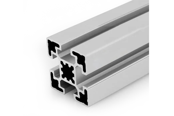
Solar Mounting Aluminium Rail 45 x 45 mm for PV Array Frames
45 x 45 mm four slot aluminium profile at about 2.55 kg/m, used as a solar mounting rail, supplied cut to length and anodised AA20 or AA25 for outdoor and coastal exposure.
| Material | Aluminium |
|---|---|
| Alloy Grade | 6063-T5 |
| Temper | T5 |
| Section Size | 45 x 45 mm, four slots |
| Slot | 8 x 8 mm groove, M10 slot nuts, four faces, 33 mm pitch |
| Length | Cut to length to +/-0.5 mm, with end caps for cut ends |
| Tolerance | Cut length +/-0.5 mm, section to EN 755-9, coating to the anodising class specified |
| Surface | Anodised AA20 or AA25 clear or black; mill finish available but not recommended for outdoor use |
| MOQ | 500 m |
| Lead Time | 15 to 25 days after deposit for mill finish, plus about a week for anodising |
| Loading Port | Shanghai / Ningbo |
| Supply Ability | 600 t per month extrusion with in-house anodising and end capping |
| Payment Terms | T/T 30% deposit + 70% before shipment | L/C at sight |
| Trade Terms | FOB | CIF | EXW |
| Certifications | Coating thickness report, material certificate to EN 10204 3.1 on request, RoHS and REACH declarations |
01How does a wind load become a rail span?
In three steps, and the middle one is where projects go wrong. Wind pressure becomes a pressure on the array, the pressure becomes a load per metre on each rail, and the load per metre becomes a span through a deflection limit. A 45 x 45 mm solar mounting aluminium rail at about 2.55 kg/m is comfortably strong for a residential array; what limits it is deflection, and deflection grows with the fourth power of the span.
Step one, for orientation only: wind pressure is roughly q = 0.5 x density x velocity squared. At 30 m/s with air at 1.25 kg/m3 that is about 562 Pa, or 0.56 kN/m2. Step two is where the real numbers live — the net pressure coefficient for an array on a roof is not 1.0, it depends on the array geometry, the roof zone and the exposure, and it can be well above the dynamic pressure in uplift. That calculation belongs to the system designer, and it is not something a profile supplier can do for you.
Everything below uses a single assumed design load so the arithmetic can be followed. It is not a design load for any particular roof, and the array has to be checked by whoever is responsible for the mounting system.
02What span does this rail actually give?
Take a worked case: a design load of 1.5 kN/m2 combining wind, snow and a safety factor, on a 1.0 x 2.0 m module of 2 m2. That is 3.0 kN per module, shared between two rails, so 0.75 kN/m on each rail. The section weighs 2.55 kg/m, which gives a cross-section of about 944 mm2 and, over a 180 mm perimeter, an average wall of about 5.25 mm.
- Design load (assumed)
- 1.5 kN/m2
- Module
- 1.0 x 2.0 m, two rails per module
- Load per rail
- 0.75 kN/m
- I (estimated)
- about 2.24 x 10^5 mm4, ignoring the slot grooves
- E, aluminium
- 70 000 N/mm2
- Formula
- delta = 5 w L^4 / (384 E I)
| Rail span | Deflection | Limit at L/200 | Verdict |
|---|---|---|---|
| 800 mm | about 0.3 mm | 4.0 mm | Comfortable |
| 1200 mm | about 1.3 mm | 6.0 mm | Comfortable |
| 1600 mm | about 4.1 mm | 8.0 mm | Acceptable, and it shows |
| 2000 mm | about 10.0 mm | 10.0 mm | At the limit, not beyond it |
| 2400 mm | about 20.7 mm | 12.0 mm | Fails — step up a section |
Two things are worth taking from that table. First, the stress is nowhere near the limit: at a 1.2 m span the bending moment gives roughly 14 N/mm2 in a 6063-T5 section that yields at well over 100 N/mm2. The rail is not close to breaking, it is only close to bending. Second, the jump from 1.6 m to 2.4 m is a factor of five, which is the fourth-power relationship doing its work. Reducing the span is always cheaper than increasing the section.
03Why does clamp position matter more than rail size?
Because there are two spans on a PV array and people only design one of them. The rail span is the distance between roof attachments and it governs the rail. The module span is the distance between the two rails under one module and it governs the module — and the module is the expensive, fragile part.
- Rails go at the module maker’s clamp zones, typically the quarter points, not wherever the roof purlins happen to be. The clamp zone drawing is in the module datasheet and it is not negotiable.
- The cantilever beyond the outer clamp is limited by the module maker, often to a quarter of the module length. A module clamped too far inboard cracks at the frame corner, and it cracks in the first windy season.
- The rail span is then whatever the purlin spacing gives, and if that is 2.4 m the rail has to be deeper — not the clamp position changed.
- Mid-clamps and end-clamps are different parts with different load paths. An end-clamp carries half the module it carries a mid-clamp, and it is the one that gets substituted wrongly.
The practical consequence: fix the module clamp positions first, then design the rail span around the purlins, then choose the section. Doing it in the other order produces a rail that is stiff enough and a module that cracks.
04What finish survives outdoors?
Not mill finish. Bare aluminium outdoors forms an oxide layer that protects it in clean air and stops protecting it near the coast, where chloride breaks the layer down. On a roof that cannot be repainted, the finish is a durability decision rather than a cosmetic one.
| Finish | Suitable environment | Life expectation | Watch out for |
|---|---|---|---|
| Mill finish | Not recommended outdoors | Stains and pits, faster near the coast | Any chloride exposure at all |
| Anodised AA15 | Inland, sheltered | Good, with staining at cut ends | Cut ends and drilled holes are bare |
| Anodised AA20 | General outdoor, moderate air | Good | Sealing quality matters as much as thickness |
| Anodised AA25 | Coastal and marine | Acceptable, with maintenance | Bare cut ends still corrode first |
| Powder coated | Coastal, and where colour matters | Good, if the pretreatment is right | Coating damage is a corrosion site, and it is insulating |
One detail matters more than the class: every cut end and every drilled hole is bare aluminium. On a rail that is cut to length on site, that is two bare ends per rail and they are exactly where water sits. End caps, or a touch-up with a suitable coating, are worth more than moving from AA20 to AA25.
05How do you earth an anodised rail?
Deliberately, because anodising is an insulator. The module frame is usually anodised aluminium as well, so a clamp pressing an anodised module frame onto an anodised rail gives you two insulators in series and no bond at all. This is the most common electrical defect on a PV array, and it is invisible.
- Use bonding clips or toothed washers that bite through the anodising at each module to rail interface. A plain clamp does not bond, however tight it is.
- Bond the rail to the structure at defined points, not by hoping the roof fixings do it.
- Provide a continuous earth conductor along the array and connect it to the equipotential bonding of the building, per the electrical design.
- Do not rely on the mid-clamp as the bond. Some are listed as bonding devices and most are not, and the difference is a listing, not a shape.
- Check continuity after assembly, not before. A bond that reads correctly on the bench can be lost when the clamp is torqued onto a coated surface.
The electrical design, the earthing arrangement and the inspection regime belong to the electrical designer and to whatever standard governs the installation. What we can do is supply a section and a finish that the bonding hardware is designed to work with.
06What about the joint between the module and the rail?
Two dissimilar metals in a wet place, which is the definition of a galvanic couple — except that on a modern array both are usually anodised aluminium, so the couple is small and the coating is doing the work. The problems appear when the hardware is not aluminium.
| Hardware | Couple with an aluminium rail | Practical note |
|---|---|---|
| Anodised aluminium clamp | None, same material | But it does not bond electrically without a toothed washer |
| Stainless steel clamp | Moderate | Common and acceptable, with a sealed interface |
| Galvanised steel clamp | Moderate, zinc is consumed first | Inspect at service; the zinc is the sacrificial part |
| Bare steel fastener | High | Avoid outdoors on an aluminium rail |
The practical rule is the same as everywhere else on aluminium: keep water out of the interface and keep dissimilar metals small in area. A stainless clamp with a bonded washer is fine. A large bare steel bracket against an aluminium rail is not.
07What is our scope?
What we supply
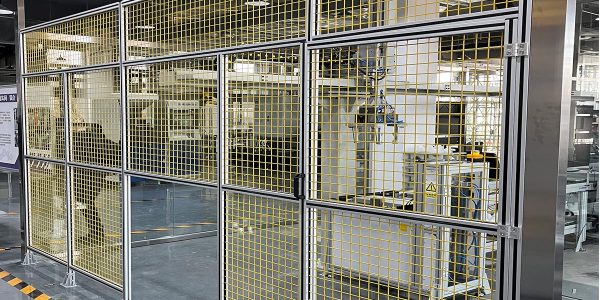
- 45 x 45 mm extrusion, cut to length
- Anodising to a specified class, with end caps for cut ends
- Drilling and slotting to a drawing
- Material certificate and dimensional report on request
- Consistent section and alloy across a project
What we do not supply or certify
- The structural design of the mounting system
- Wind and snow load calculation for a specific site
- Compliance with the structural or electrical standard that applies
- The earthing design and the inspection regime
- Any statement that a finished array is safe or compliant
A mounting system is a structural product with a load calculation behind it, and that calculation depends on the site. We supply the extrusion that goes into it, to the section tolerance and the alloy specified, and we will cut and machine it accurately. The system, and its compliance, is the system designer’s.
PV rail checklist
- Module size, and the clamp zones from the module datasheet
- Rails at the quarter points, or wherever the module maker requires
- Cantilever beyond the outer clamp, against the module maker’s limit
- Purlin or roof attachment spacing, which sets the rail span
- Design load for the site, from the system designer
- Rail span against the deflection limit, and the section that meets it
- Finish class, and the distance to the coast
- End caps or touch-up for every cut end and drilled hole
- Bonding method at each module-to-rail interface
- Earth conductor route and connection to the building bonding
08Questions from installers and system designers
Related sections and categories
Browse 45 Series Aluminium Profiles, Strut Profiles, or see the 45 x 45 mm four slot section for the full section data, and the 45 x 90 mm six slot heavy section when the purlin spacing forces a longer rail span.
What span can a 45 x 45 aluminium solar rail cover?
About 1.2 m comfortably and about 2.0 m at an L/200 deflection limit, for an assumed 0.75 kN/m load per rail. Stress is not the limit — deflection is, and it grows with the fourth power of the span.
What finish should a solar mounting rail have?
Anodised AA20 or above for general outdoor use, and AA25 near the coast. Mill finish is not suitable outdoors. End caps matter because every cut end is bare aluminium.
Does an anodised rail need special earthing?
Yes. Anodising is an insulator, so a plain clamp on an anodised module frame and an anodised rail gives no electrical bond. Use bonding clips or toothed washers that bite through the coating.
How much does 45 x 45 aluminium profile weigh?
Approximately 2.55 kg/m, with four 8 x 8 mm slots on a 33 mm pitch and M10 slot nuts.
Why do PV modules crack at the frame corner?
Usually because the clamp position is outside the module maker’s clamp zone, or the cantilever beyond the outer clamp is too long. It is a module support problem rather than a rail problem.
Do you design the mounting system?
No. We supply extrusion cut and finished to your drawing. The structural design, the load calculation and compliance with the applicable standard are the system designer’s scope.
What to send for a PV rail quote
- Module size and the clamp zone drawing from the module datasheet
- Rail spacing under the module, and the purlin spacing
- Design load, if the system designer has already calculated it
- Rail span and the deflection limit being applied
- Section, or the span so we can suggest one
- Finish class, and the distance to the coast
- Cut list with lengths, and whether ends need caps
- Drilling or slotting required
- Quantity per project, and whether repeat projects are expected
Send the purlin spacing and the module clamp zones together. Those two numbers decide the section, and sending one without the other usually means the quote has to be redone.
Send the purlin spacing and clamp zones
Tell us the module size, the purlin spacing and the finish class. We will confirm the rail span against a deflection limit and quote the cut list with end caps.
Request a quotationRelated Products
 45 x 180 mm Aluminium Extrusion for Typhoon-Zone Frames
45 × 180 mm aluminium extrusion in 6063-T5 for outdoor frames in the Philippine…
 Aluminium Profile for Sale: 45 x 60 mm Cut to Length, No Minimum Run
45 x 60 mm aluminium profile in 6063-T5, sold by the length or by…
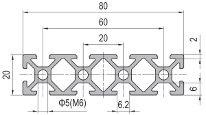 20 x 80 mm Narrow Aluminium Profile for Textile and Diamond Machinery
20 x 80 mm ten slot narrow aluminium profile in 6063-T5 for machinery where…
 45 x 180 mm Aluminium Extrusion: Arrival Inspection for Importers
45 × 180 mm aluminium extrusion in 6063-T5 for importers clearing at Nhava Sheva.…
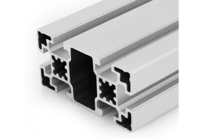 45 x 90 mm Aluminium Profile for Pharma Cleanroom Framing
45 x 90 mm aluminium extrusion in 6063-T5 for GMP cleanroom framing. Six 10.2…
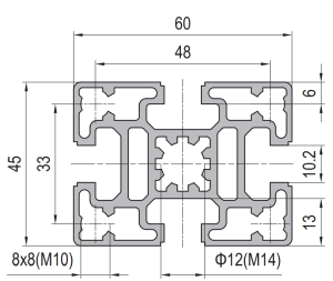 45 x 60 mm Aluminium Profile for Textile Machine Frames
45 x 60 mm four-slot aluminium extrusion in 6063-T5 for loom, winder and conveyor…
 Aluminium Company Profile: How a 90 x 90 mm Section Is Made and Inspected
90 x 90 mm eight-slot aluminium extrusion in 6063-T5 for machine bases, robot pedestals…
 120 x 120 mm Aluminium Profile for Automotive Line Tooling
120 x 120 mm twelve-slot aluminium extrusion in 6063-T5 for welding jigs, assembly fixtures…
