Moment of Inertia and Section Modulus of T-Slot Profiles
A typical 20 × 20 mm T-slot bar in 6063-T5 carries about 0.49–0.50 kg/m with Ix = Iy ≈ 0.72–0.74 cm⁰ — values taken from the nominal section under EN 755-9 geometry, not from the outline alone. Copy I and Z from the supplier drawing into the deflection and stress check before you freeze the span.
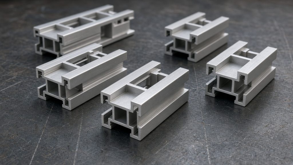
Short answer
Use moment of inertia I for deflection and section modulus Z for bending stress. For a common 2020 (6 mm slot) expect Ix = Iy ≈ 0.72–0.74 cm⁰, Zx = Zy ≈ 0.72 cm and mass ≈ 0.49–0.50 kg/m at 2.70 g/cm⁵; heavier 4040 sections sit near 8–14 cm⁰ depending on the internal web. Screen mid-span deflection with δ = F·L³/(48·E·I) and E ≈ 69 GPa for 6063-T5. Thermal movement of 6063 is about 23.4 µm/m·°C: a 3 m rail through +40 °C grows ≈ 2.8 mm if free. Bolted T-slot fatigue is usually joint fretting and preload loss, not parent-bar endurance — keep dry torque in the M6 5–8 Nm and M8 13–20 Nm bands and recheck after vibration. Extrusion tolerances EN 755-9: wall ±0.15 mm, straightness 1.5 mm/m, twist 2°. Fabrication: cut length ±0.5 mm, hole position ±0.2 mm, end square within 0.3 mm. Site heavy rail: 45 × 90 mm six-slot, 6063-T5, 4.10 kg/m, I ≈ 68 cm⁰.
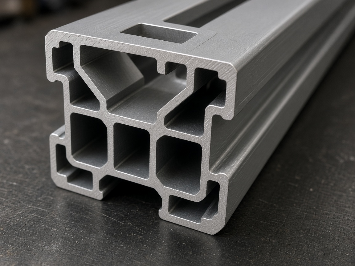
What is the moment of inertia of a 2020 t-slot profile
A standard 20 × 20 mm T-slot (6 mm slot) has Ix = Iy ≈ 0.72–0.74 cm⁰ about the centroidal axes — roughly one-tenth of a typical 4040, which is why 2020 is a light frame member, not a metre-class beam.
I measures how the area is distributed against bending; it enters every elastic deflection formula and must come from the supplier’s nominal section (or a measured DXF), not from a solid 20 mm square. Internal ribs, slot depth and corner radii move I by tens of percent between “same size” catalogues. Orient rectangular bars so the larger I fights the primary moment. For screening, keep E = 69 GPa and compare δ to L/500 or L/360 before you approve the cut list.
| Section (typical) | Mass (kg/m) | Ix ≈ (cm⁰) | Iy ≈ (cm⁰) | Role |
|---|---|---|---|---|
| 2020 | 0.49–0.50 | 0.72–0.74 | 0.72–0.74 | Light frames, braces |
| 2040 | ≈0.90 | ≈4.6 | ≈1.4 | Strong axis as short beam |
| 3030 | 0.75–1.0 | 2.4–3.3 | 2.4–3.3 | Light benches, guards |
| 4040 | 1.5–1.7 | 8–14 | 8–14 | Industrial bays |
| 4080 (strong) | ≈3.0–3.4 | ≈63–74 | ≈18–21 | Long spans, gantries |
| 45 × 90 six-slot | 4.10 | ≈68 | (weaker) | Heavy top / guard rail |
What is the section modulus of 2020 aluminium extrusion
Section modulus Z for a typical 2020 is about 0.72 cm on both axes — use it for bending stress σ = M/Z, while I stays the number for deflection.
Z = I/c where c is the distance from the neutral axis to the extreme fibre. Two bars with similar I can differ in Z if one puts more metal farther out. Yield of 6063-T5 is not the usual limit on light frames: joints slip and deflection limits trip first. Still publish Z on the drawing so a stress check can be run under impact or concentrated bracket loads. Heavier 4040 sections often sit near Z ≈ 4–7 cm depending on the web; do not mix catalogue families when you copy the number.
| Section | Zx ≈ (cm) | Zy ≈ (cm) | Use Z for | Use I for |
|---|---|---|---|---|
| 2020 | 0.72 | 0.72 | Local bending stress | Deflection screen |
| 2040 | ≈2.3 | ≈1.3 | Strong/weak axis stress | Orientation choice |
| 3030 | 1.6–1.8 | 1.6–1.8 | Bracket pad checks | Bay deflection |
| 4040 | 4–7 | 4–7 | Impact / point load | 1–2 m industrial bays |
| 4080 strong | ≈16–19 | ≈9–10 | High moment members | Long spans |
| 45 × 90 | from I≈68 | weaker axis | Heavy rail stress | Top / guard deflection |
What is the coefficient of thermal expansion effect on a 2020 frame
6063 expands at about 23.4 µm per metre per °C (20–100 °C), so a free 2020 rail of length L grows ΔL = α·L·ΔT — roughly 0.94 mm per metre for a +40 °C rise.
That movement is small on a 0.5 m brace and obvious on a 3–6 m perimeter fence or conveyor side rail. If the frame is restrained by steel floor plates, fixed walls or locked mitres, expansion turns into stress and can open joints or bow panels. Leave sliding slots or slotted foot holes on long runs; give polycarbonate and acrylic panels perimeter clearance so the aluminium does not crush them. Installation temperature matters: a kit built at 10 °C and run at 50 °C near an oven needs the full ΔT in both directions. Mixed aluminium–steel assemblies need differential checks; steel’s α is roughly half.
| Length L | ΔT | ΔL (free, α=23.4) | Design action |
|---|---|---|---|
| 1.0 m | +20 °C | ≈0.47 mm | Usually absorbed in joints |
| 1.0 m | +40 °C | ≈0.94 mm | Watch panel gaps |
| 3.0 m | +40 °C | ≈2.8 mm | Slotted feet / expansion joint |
| 6.0 m | +40 °C | ≈5.6 mm | Break rails or slide mounts |
| 3.0 m | −20 °C | ≈−1.4 mm | Check seal engagement |
| Panel 1.0 m PC | +40 °C | higher than Al | Oversized holes / soft clamps |
What is the fatigue behaviour of a bolted 2020 joint
Fatigue on a bolted 2020 frame almost always appears as joint fretting, T-nut walk and preload loss — not as a classic through-crack in the parent bar at catalogue endurance stress.
The light lip and small contact area under an M5/M6 T-nut mean cyclic racking works the clamp face. Keep dry torque in the maker’s band (working plant practice often sits near 3–6 Nm for M5 on 2020 and 5–8 Nm for M6 on larger series; M8 13–20 Nm on 40-series). Recheck torque after first transport and after the first week of vibration. Prefer gussets or end-tapped butt fasteners where the joint sees reversing load; a single thin L-bracket on 2020 is a positioning joint, not a fatigue-rated machine base. Anodised slots change friction, so the same torque does not guarantee the same preload as mill finish. Parent-bar fatigue data (RR Moore style) is a poor substitute for a joint test on the actual bracket and nut.
| Joint detail | Fatigue behaviour | Mitigation |
|---|---|---|
| Single thin L on 2020 | Preload loss, lip wear | Gusset or upsize series |
| M6/M8 T-nut + bracket | Good if torqued and locked | 5–8 / 13–20 Nm; recheck |
| Blind internal connector | Lower clamp area | Not for reversing primary load |
| End tap + butt fastener | Better axial cyclic path | End square ≤0.3 mm |
| Through-bolt both walls | High if washers seat | Planned holes ±0.2 mm |
| Anodised vs mill | Friction shift → preload shift | Torque to finish-specific chart |
RFQ checklist — section data
- Section and axis — 2020 / 3030 / 4040 / 45 × 90 and which I you bend about.
- I and Z source — supplier drawing or DXF, not a generic web table alone.
- Load case — mid-span F, uniform load, or bracket point load; δ limit.
- Temperature range — install T and service ΔT for long rails and panels.
- Joint duty — static, vibrating, or reversing; torque standard.
- Tolerances — EN 755-9 wall ±0.15 mm, straightness 1.5 mm/m, twist 2°; cut ±0.5 mm, holes ±0.2 mm, square 0.3 mm.
- Documents — mill certificate and section property sheet with the quote.
Ask for I and Z on the quotation drawing for the exact die, not for “2020 class.” Internal webs differ enough to move deflection by a full serviceability class.
Four ways the numbers mislead
Related on this site
- how die cost amortises per meter — cost of locking one high-I section
- minimum order with a new die — when a custom stiff section needs tooling
- die making adds 7–12 days — calendar before the first property sheet
- who owns the die — reuse rights on a custom I-section
Terms used in this article
- Moment of inertia (I)
- Second moment of area about a centroidal axis; governs elastic bending deflection with E.
- Section modulus (Z)
- I divided by the distance to the extreme fibre; used for bending stress σ = M/Z.
- EN 755-9
- European tolerance standard for extruded aluminium bars, tubes and profiles.
- CTE (α)
- Linear coefficient of thermal expansion; ≈23.4 µm/m·°C for 6063 in the 20–100 °C band.
- Preload
- Clamping force from correct fastener torque; critical to joint fatigue life.
- Strong axis
- The bending axis with the larger I on a rectangular profile.
Questions buyers ask
What standard are the tolerances measured against?
Extrusion geometry is commonly held to EN 755-9: wall thickness ±0.15 mm on light walls, straightness 1.5 mm/m and twist 2° unless the drawing states otherwise. Fabrication after sawing is separate: cut length ±0.5 mm, hole position ±0.2 mm, end square within 0.3 mm. Ask which standard is on the inspection report before you compare two quotes.
Can you supply a mill certificate?
Yes — a 3.1 mill certificate for alloy and temper (typically 6063-T5 for T-slot) can ship with the lot. For structural or export jobs request the certificate number on the packing list and keep it with the section-property drawing so I and Z stay tied to the poured heat.
What is the minimum wall thickness?
Minimum wall is a die and alloy-flow limit, not a single catalogue number. Light 2020 webs often sit near 1.5 mm on diagonals; structural series use thicker webs (often 2 mm and up) where brackets and anchors bear. State the minimum wall on the RFQ if you need a structural lip; do not assume every “2020” shares the same web.
How is weight per metre calculated?
Mass per metre is cross-sectional area × density. For aluminium use 2.70 g/cm⁵ on the nominal section: a 2020 near 180–185 mm² yields about 0.49–0.50 kg/m. Anodising adds little mass; powder coating adds more. Invoice weight may use weighed bars — compare to the calculated value on the drawing if freight is quoted per kilogram.
Send the span and deflection limit
Share bay length, load case and allowable δ. We return the matching section with I, Z, mass and EN 755-9 / cut tolerances on the quotation drawing.
Request section dataRelated reading
Twelve more engineering notes from this blog, picked for this article — plus every category below.
 Engineering Design4040 vs 4080 Aluminium Profile: Which for Your Frame
 Engineering DesignWho Owns the Extrusion Die After Tooling Is Paid?
 ApplicationsWhere Modular Aluminium Framing Works: A Load-Tier Map Instead of an Industry List
 ApplicationsLean Pipe vs T-Slot Profile: Two Interface Philosophies, Not Two Generations
 Engineering DesignCross-Brand T-Slot Compatibility: Interchangeability Is a Hardware Question
 ApplicationsAluminium Profile Applications
 ApplicationsAluminium Profiles for Automation Equipment Frames: Design From the Assembly Floor
 Engineering DesignModular Aluminium Components: Where the System Saves Money and Where It Costs You
 Quality and InspectionEuropean Anodised Aluminium Specification: What Should a Purchase Order Contain?
 Sourcing and ProcurementAluminium Profile Quote: What Changes the Number by Quantity
 Materials and EngineeringAluminium Corrosion: Why a Salt Spray Number Is a Ranking, Not a Life
 Machine SafetyAluminium Profile Machine Guards: Size the Frame from the Energy, Not from the Mesh
