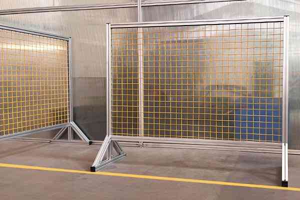
An aluminium profile has no safety certification. It cannot have one, because it is not a safety device — it is a structural carrier that happens to be extremely well suited to building guards. The distinction sounds pedantic until you read a supplier catalogue that sells a “safety fence system” as though the profile were the safety feature, and then watch a plant install one with 50 mm mesh at 200 mm from a hazard.
What makes a guard safe is a chain of design decisions that sit entirely outside the profile: what the hazard is and how severe, how far away the guard has to be so that a limb cannot reach through it, how much impact it has to resist, what the panel is made of, and how people get in when they legitimately need to. Get the chain right and almost any well-made profile system will do the job. Get it wrong and the most expensive framing in the catalogue will not save you.
This guide is written for the safety, production or maintenance engineer who has to specify and then defend a guarding installation — typically someone who owns a CE technical file or an internal safety standard, and who will be asked to demonstrate that the guard is adequate rather than merely present. It covers the standards that apply, the risk assessment that has to come first, the safety distance calculation that is most often got wrong, how to select a profile section and a panel material, how to handle access and interlocking, and what to check before you sign the installation off.
Guarding is the second choice, not the first
One framing point worth establishing early, because it changes how the whole problem is approached. Guarding is the second choice in the hierarchy of risk reduction, not the first. The first is designing the hazard out altogether, and the third is telling people about it. A guard is what you build when you cannot remove the hazard and cannot rely on information alone. Starting from the guard means you will end up guarding hazards you could have eliminated, which is expensive and, in the long run, less safe.
Quick answer
Ten points that decide whether a guard is actually safe
Items 1 and 2 set the approach. Item 3 is the requirement most often missed and the one with the worst consequences, and item 8 is the constraint that catches out otherwise careful designs.
The profile is a carrier, not a safety device No aluminium profile carries a safety certification. The safety comes from the design: distances, impact resistance, panel material and interlocking. Specify the design and let the profile be a structural choice.
Risk assessment comes first, and it is not optional The general machinery safety standard sets out an iterative method: identify hazards, estimate and evaluate risk, then reduce risk in a defined order. Every later decision — distance, section, panel, interlock performance level — is an output of that assessment.
Mesh aperture sets the minimum distance The safety distance standard relates the size of an opening to the minimum distance from that opening to the hazard zone. A large aperture needs a large distance. This is the single most frequently violated requirement in workshop fencing.
Safety distance is measured to the hazard, not to the machine Measure from the opening to the nearest reachable hazard point, including rotating parts, pinch points, hot surfaces and live conductors. Not to the machine’s outer panel.
Span and impact both drive the section, and impact usually wins For a perimeter fence containing people, a modest section at sensible post spacing is usually adequate. For a guard that has to contain an ejected workpiece or resist a person falling against it, the required impact energy determines the section, not the span.
Panel material is a safety decision, not an aesthetic one Polycarbonate absorbs impact. Acrylic is clearer and more scratch-resistant and can shatter into sharp fragments. Steel mesh has no static problem and good airflow. The choice depends on what the panel has to resist.
Fixed guards need a tool; movable guards need an interlock A fixed guard that can be removed by hand is not a fixed guard. A movable guard on a hazard with a run-down time needs guard locking, not just interlocking, because the hazard is still present after the guard is opened.
Series-wiring interlocks reduces the achievable performance level Interlock switches wired in series share diagnostic coverage, so the achievable performance level falls as more switches are added. This is a real constraint on large installations and is routinely overlooked.
Noise control is mass, damping, sealing and isolation Not a property of the profile. An enclosure reduces noise through panel mass, damping layers, sealed gaps and vibration isolation — and a small unsealed gap can undo much of the benefit.
The technical file is part of the deliverable Guard design, verification results, interlock performance level and residual risk information belong in the machine’s technical documentation. A guard that cannot be shown to be adequate is, for compliance purposes, not adequate.
Framework
The standards that apply, and what each one decides
Machine guarding is one of the more thoroughly standardised areas of engineering, which is good news: the questions have been thought about, and the answers are written down. The list below is the working set for a guarding project. Each standard decides a specific thing, and knowing which one decides what is most of the battle.
| Standard area | What it decides | Where it enters the project |
|---|---|---|
| General machinery safety and risk assessment | The method: hazard identification, risk estimation and evaluation, and the order in which risk reduction measures are applied | Before anything is drawn. The output is the list of hazards and the required risk reduction for each. |
| Safety distances | The minimum distance from an opening or a reach-over point to the hazard zone, as a function of the opening size and the limb involved | When the guard geometry is set. It fixes how far away the guard has to be and therefore how much floor space the installation consumes. |
| Guard design and construction | Requirements for fixed and movable guards: impact resistance, robustness, visibility, avoidance of new hazards, and the holding and fixing arrangements | When the guard is designed. It is the standard that governs whether the guard itself is fit for purpose. |
| Interlocking devices | Selection and design of interlocking devices associated with guards, including defeat prevention and the use of guard locking | When access arrangements are designed. It is where the choice between a mechanical switch, a magnetic switch and a coded non-contact switch is made. |
| Safety-related control system performance | The performance level required of the safety function, from the risk assessment, and how architecture, diagnostics and component reliability combine to achieve it | When the interlock circuit is designed. It determines whether a simple switch is sufficient or a redundant, monitored architecture is required. |
| Safety signs and symbols | The graphical symbols and safety colours used on guards and on the machine | At installation. It governs the residual risk information that must be visible to the operator. |
| Emergency stop | Requirements for the emergency stop function, its location and its behaviour | At installation, and it is a separate function from guarding — an emergency stop does not substitute for a guard. |
| European machinery legislation | The legal framework for placing machinery on the market, including the technical file and conformity assessment requirements | Throughout. Note that the European framework has moved from a directive to a regulation with a transition period, so confirm which instrument applies on your date of placing on the market. |
Two clarifications that prevent a lot of confusion. First, an emergency stop is not a guarding measure: it is a complementary protective measure, and a machine that relies on an operator pressing a button in time is not guarded. Second, a guard and an interlock are different things: the guard is the physical barrier, the interlock is the control function that stops the machine when the guard is opened. Both are needed on a movable guard, and they are specified in different standards.
Method
Start with the risk assessment
Every design decision in this article is downstream of the risk assessment. The general machinery safety standard defines an iterative method, and it is worth following it literally rather than treating it as paperwork, because the outputs it produces are exactly the inputs the rest of the design needs.
Identify the hazards
For each task the machine performs, and each task a person performs on it, list the hazards: mechanical (crushing, shearing, cutting, entanglement, drawing-in, impact, ejection), thermal, electrical, noise, vibration, radiation, and hazards from materials and substances. Do it by task, not by machine, because hazards appear during cleaning, jam clearing, tool changing and maintenance rather than during normal running.
Estimate and evaluate the risk for each hazard
For each hazard, estimate severity of harm and probability of occurrence, considering exposure frequency and duration, and the possibility of avoiding the harm. Then evaluate: is the risk acceptable, or must it be reduced? The result is a ranked list, and the ranking is what tells you where to spend design effort.
Reduce risk in the defined order, starting with elimination
First, inherently safe design: remove the hazard or make it unreachable by geometry, so that no guard is needed at all. Second, safeguarding: fixed guards, movable guards with interlocks, protective devices such as light curtains, and complementary measures. Third, information for use: warnings, signs, training and procedures. Working down this order is not a preference; it is the method.
Re-assess after each change
Guards create hazards of their own: pinch points between the guard and the machine, sharp edges, entrapment, restricted visibility, and reduced access for maintenance that leads to guards being removed and not replaced. Every iteration goes back to step one.
Record the required performance level for each safety function
Where a guard’s protection depends on a control function — an interlock stopping the machine — the assessment has to produce a required performance level for that function. That figure is what the interlock circuit is then designed against, and it is the link between the risk assessment and the electrical design.
Document it, because it is the evidence
The risk assessment is part of the technical file. It is what turns “we thought this was adequate” into a defensible engineering position, and it is the first document requested after an incident.
Design for the maintenance task, not just the running machine
One failure mode deserves naming because it is so common and so consequential. Guards are designed for normal operation and then defeated during maintenance, cleaning and jam clearing, because the guard makes those tasks slow and the production pressure makes them urgent. The risk assessment has to consider reasonably foreseeable misuse, which includes a person opening or removing a guard to clear a jam. If the assessment concludes that access is needed, the answer is not a stronger warning sign — it is a design that allows access safely, such as an interlocked access door with guard locking, or a procedure that removes the need to enter at all. A guard that will be bypassed is not protection.
Geometry
Safety distances: the requirement most often missed
This is the section to read twice. The safety distance standard relates the size and shape of an opening in a guard to the minimum distance between that opening and the hazard zone. The logic is straightforward: a person can reach further through a larger opening, so a larger opening requires the guard to be further away. An installation that ignores this can have a guard that looks correct, is well made, is bolted down properly, and does not prevent a hand reaching a rotating shaft.
The table below gives the shape of the relationship for reaching through regular openings with the upper limb. It is deliberately presented as a simplified guide to the order of magnitude, because the actual values depend on the opening shape (slot, square, round), the limb, and the age group being considered, and the standard tabulates each case separately.
| Opening size (approximate) | What can pass through | Minimum safety distance to the hazard zone |
|---|---|---|
| Up to about 4 mm | The tip of a finger cannot enter usefully; a thin probe or wire could | Very small — a few millimetres. An aperture this size is the basis of fine mesh guarding. |
| Around 4–8 mm | A fingertip, and part of a finger | On the order of 10–20 mm. Fine mesh guarding keeps the distance requirement small. |
| Around 8–12 mm | A finger, up to the first joint and beyond | On the order of 80–100 mm. This is where medium mesh starts to require real standoff from the hazard. |
| Around 12–20 mm | A finger and part of the hand | On the order of 120 mm or more. |
| Around 20–30 mm | The hand, up to the thumb base | On the order of 200 mm. A common mesh size for general workshop fencing, and a common source of inadequate standoff. |
| 30 mm and above | The whole hand, and progressively the arm | Several hundred millimetres, rising towards 850 mm and beyond as the opening grows. At this point the opening is large enough that the guard must be treated as a reach-over or reach-through boundary rather than as a mesh. |
These figures are indicative and must not be used as design values. The safety distance standard tabulates the exact distances for each opening geometry, limb and age group, and it also covers reaching over the top of a guard, reaching around an edge, and the lower limbs. Confirm the applicable values against the current edition of the standard for your specific configuration, and remember that the distance is measured to the nearest reachable hazard point — which may be inside the machine, not at its outer surface.
The practical consequence of this table is that mesh size and standoff are traded against each other, and the trade has a cost. Fine mesh (under 8 mm) permits a guard close to the machine, which saves floor space but reduces visibility and airflow and costs more per square metre. Coarse mesh (20–30 mm) is cheaper and more transparent but requires a standoff that can add hundreds of millimetres to the footprint of the installation. Deciding this early, from the reach calculation rather than from what is in stock, is what prevents a late redesign.
Do not forget reach-over
There is a second geometry problem that the mesh table does not cover and that is equally common: reaching over the guard. A fence that is high enough to stop someone walking through may still be low enough for a person to reach over, and the safety distance standard has separate tables for that case based on the height of the protective structure and the height of the hazard zone. A guard height that satisfies one requirement may not satisfy the other, and the check is not optional for a perimeter fence around a hazard zone.
Structure
Choosing the profile section
Profile selection for guarding is a deflection problem more often than a strength problem. A section that will not break under the load may still deflect enough to contact the machine, to open a gap that violates the safety distance, or to be pushed aside far enough to permit access. The design question is therefore not “will it hold?” but “how far will it move, and does that movement matter?”
| Installation type | What drives the section | Practical guidance |
|---|---|---|
| Perimeter fence around a robot cell or process area, containing people | Post spacing and the deflection limit; modest impact energy | A light-to-medium square section at sensible post spacing, anchored to the floor, with a mesh aperture that satisfies the safety distance for the standoff available. Panel width often sets the spacing. |
| Guard panel that must contain ejected material | Impact energy at the design point, and the requirement that the panel must not be breached or driven into the hazard | A heavier section, more closely spaced posts, and a panel material chosen for impact absorption. The section follows the impact case, not the span. |
| Tall enclosure with a roof or canopy | Combined wind and impact loading, plus the stiffness of the roof-to-post connection | Strong-axis orientation for the posts, gusseted connections, and a specific check on the roof connection, which is where tall light structures usually fail. |
| Access gate or door frame | Repeated cycling, hinge and latch loads, and the fact that the frame carries the interlock | A stiffer section than the adjacent panels, because the door frame is loaded every time it is used and it carries the safety device alignment. |
| Adjustable or frequently reconfigured guarding | Connection reliability after repeated assembly, and the need to re-verify safety distances after each change | Modular profile is the right answer here, with a documented reconfiguration procedure that includes re-checking the safety distance and re-testing the interlock. |
The last row is the honest assessment of what modular profile guarding is actually good at. Its real advantage is not that it is lighter or cheaper than welded steel — it is often neither — but that it can be reconfigured, extended and partially dismantled without cutting or welding. That advantage is worth paying for in a plant that changes its layout, and it is largely wasted in a permanent installation.
Materials
Choosing the panel material
The panel is what a person actually encounters, and in most guarding failures it is the panel rather than the frame that has been inadequately specified. The guard design standard requires the guard to resist foreseeable impact and to provide adequate visibility, and different panel materials satisfy those two requirements to very different degrees.
| Panel material | Impact behaviour | Visibility | Watch out for |
|---|---|---|---|
| Polycarbonate sheet | Very high impact resistance; it absorbs energy by deforming rather than shattering. The reference material where impact and visibility are both required. | Good, with some optical distortion at thickness. Clarity is lower than acrylic. | It scratches easily, so it should not be cleaned with abrasive cloths. Chemical resistance is limited: some solvents, alkalis and aggressive cleaners attack it. It needs a UV-stabilised grade outdoors. Mount it so it can flex rather than clamping it rigidly on all four edges, or the impact resistance is not realised. |
| Acrylic sheet | Clearer and more scratch-resistant than polycarbonate, but brittle under impact and capable of shattering into sharp fragments. | Excellent optical clarity. | It is the wrong choice where the panel may be struck. Where clarity is essential and impact is possible, use a laminated or toughened glass construction, or a polycarbonate panel, rather than plain acrylic. |
| Toughened or laminated glass | Toughened glass breaks into small blunt fragments rather than shards; laminated glass retains the fragments on an interlayer. | Excellent, and resistant to scratching and to most cleaning chemicals. | Mass and cost. Heavy, and requires a frame and mounting designed for the weight. Also requires edge protection and careful handling. |
| Steel wire mesh | High impact resistance and good energy absorption; deforms rather than fracturing. | Good but reduced compared with a clear panel; adequate for seeing whether a machine is running, less good for inspecting detail. | The aperture governs the safety distance, so mesh size and standoff must be designed together. Check the coating or finish for corrosion, and check that the mesh is tensioned and fixed so it cannot be peeled back from an edge. |
| Perforated or solid aluminium sheet | Good, and predictable. Solid sheet gives the highest containment; perforated sheet trades some containment for airflow and visibility. | Poor to moderate. Solid panels are opaque and require separate vision panels. | Noise: a large unsupported sheet acts as a diaphragm and radiates sound. Where noise matters, a solid panel needs damping or a composite construction. |
| Composite and acoustic panels | Varies; the structural performance comes from the facings and the core. | Depends on the facing; some acoustic constructions include a transparent or perforated facing. | The acoustic benefit is only realised if the enclosure is also sealed and the panels are isolated from the machine’s vibration. A perforated facing without an absorptive layer behind it does not absorb much. |
Two notes on mounting that apply to every transparent panel. First, a clear panel that is rigidly clamped on all four edges is far more brittle in service than the same panel mounted with allowance for movement, because the impact energy has nowhere to go. Second, the panel fixing must not itself be a projection or a sharp edge that creates a new hazard, and it must be arranged so the panel cannot be pushed inward into the hazard.
Two details that decide service life
On static and on cleaning, two practical points that come up in real plants. Steel mesh and aluminium panels have no static accumulation problem and are the safer choice in an area where dust or solvent vapour is present, whereas a large polymer panel can accumulate charge. And a clear panel that is cleaned with the wrong chemical will craze or cloud within months, which is why the cleaning instruction belongs on the guard, not only in the manual.
Control functions
Access, interlocking and guard locking
A guard with no way in is a guard that will be removed. Access design is therefore part of the safety design, and it is where the control function enters the project. The interlocking standard covers the selection of the devices; the control system standard covers the performance the circuit has to achieve.
Fixed guards
A fixed guard is one that can only be opened or removed with a tool. Two requirements follow. The fasteners must genuinely require a tool — thumb-screws, quarter-turn catches and hand knobs do not qualify, and a fixed guard held by them is a movable guard without an interlock. And the fasteners should remain attached to the guard when it is removed, so that a guard taken off for maintenance can be put back without a search for lost bolts. Where a guard is frequently removed, the honest design is an interlocked access panel rather than a fixed guard with a convenient fastener.
Movable guards and interlocking
A movable guard has to be interlocked so that the machine cannot operate while it is open. The interlocking standard distinguishes device types and, crucially, addresses the prevention of defeat. The practical selection points are these:
- Positive-mode mechanical switches have a physical actuator that is mechanically forced open. They are robust and predictable, but they can be defeated with a spare actuator or a piece of tape, which is why coded versions exist.
- Non-contact magnetic switches are convenient and tolerant of alignment, but they are also the easiest type to defeat with a magnet, and the interlocking standard treats that as a foreseeable misuse. They are a poor choice where defeat is plausible and the risk is high.
- Coded non-contact switches (inductive or RFID-based, with a uniquely coded actuator) are substantially harder to defeat and are the usual choice where the risk assessment calls for a high performance level and where defeat is foreseeable.
- Guard locking is required where the hazard has a run-down time — a spindle that coasts, a robot that completes a motion, a press that returns. Interlocking alone stops the machine when the guard opens, which is not enough if the hazard persists after the stop command. The guard must remain locked until the hazard has ceased, and the lock release must be based on a measured run-down time rather than an assumption.
- The alignment problem. A modular profile guard door is a moving part on a frame that can be reconfigured, and an interlock actuator whose alignment drifts will eventually either fail to detect closure or be defeated to make production possible. Design the door frame stiffly, mount the actuator so that its alignment is not dependent on the hinge, and check alignment after every reconfiguration.
The series-wiring constraint
Large installations often have many interlocked access points, and the convenient way to wire them is in series into a single safety input. This is permitted, but it has a consequence that is frequently overlooked: series connection reduces the diagnostic coverage the system can achieve, and therefore reduces the achievable performance level for the safety function. The more switches in the chain, the larger the reduction. On a small installation this may be irrelevant; on a cell with a dozen doors and a high required performance level, series wiring can make the requirement unachievable no matter how good the individual switches are.
Performance level is a circuit property
This is the point at which a guarding project most often needs an electrical engineer rather than a mechanical one. The required performance level comes from the risk assessment, and whether the circuit achieves it depends on architecture, redundancy, monitoring and the diagnostic coverage of the chosen devices — not on the brand of the switch. Specify the required performance level first, design the circuit to meet it, and verify it. Do not select switches first and then assume the arrangement is adequate, which is the order in which this is usually done and the reason it usually fails an audit.
Side effects
Noise, ventilation and the things a guard changes
A guard does more than keep people out. It changes the acoustic environment, the airflow, the visibility and the maintenance access around a machine, and each of those changes has to be designed rather than discovered. The most commonly claimed benefit in supplier literature — reduced noise — is also the most commonly unrealised, because it depends entirely on how the enclosure is built rather than on what it is built from.
How an enclosure actually reduces noise
The profile system is genuinely useful here, and this is one of the few places where the framing material contributes directly to a performance requirement. The T-slot is a protected route for cables and for sensor wiring to the interlocks; it accepts acoustic panel fixings and resilient mounts without additional drilling; and it allows an enclosure to be opened, extended or partially dismantled for maintenance without cutting. That last point matters more than it sounds, because the alternative to a serviceable enclosure is an enclosure that gets cut open.
Acceptance
Verification: what to check before you sign it off
Guarding is one of the few areas where the installation can look complete and still fail a compliance review, because the failure is usually in a dimension or a function rather than in a visible defect. The checklist below is organised so that the geometric and functional checks come before the documentation, because that is the order in which an auditor will work.
How guarding projects actually fail
Two closing observations about how guarding projects actually fail. The first is that the failure is almost never a single dramatic omission; it is a collection of small ones — a mesh size chosen from stock rather than from a calculation, an actuator alignment that drifted, a locking time copied from a previous project, a sign that was never fitted. Each is trivial in isolation. The second is that the design that passes an audit and the design that protects a person are usually the same design, but not always: a guard can satisfy a checklist and still be defeated by the people who have to work behind it every day. The most reliable way to close that gap is to involve the operators and the maintenance technicians in the design review. They know which guards get removed, and they will tell you if you ask before the concrete is poured rather than after.
FAQ
Frequently asked questions
Guard it with a specified frame
Framing and machined parts for machine guarding
A guard is a structure before it is a standard. The sections below carry the stiffness, slot geometry and machining capability that the enclosure in this design guide is built from.
Building guarding or perimeter fencing to a standard?
Send us the hazard, the required safety distance, the mesh or panel specification and the impact basis. We will quote the profile, the panels, the hinges and the interlock mountings machined to your drawing, and supply the section properties and panel data your technical file needs.
Related reading
Twelve more engineering notes from this blog, picked for this article — plus every category below.
 Applications40×40 Aluminium Profile: Where It Works, Where It Fails, and Why
 ApplicationsLean Pipe vs T-Slot Profile: Two Interface Philosophies, Not Two Generations
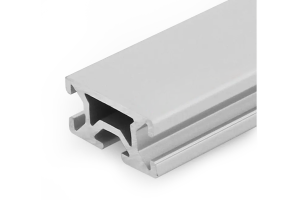 ApplicationsAluminium Profile for LED Strips: A Heat Sink First, a Housing Second
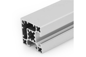 ApplicationsAluminium Workbench Fit-Out: When the Accessories and the Joints Compete for the Same Slot
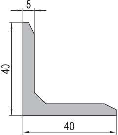 ApplicationsHow to Choose the Right 4040 T-Slot Aluminium Profile for Industrial Applications
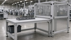 ApplicationsBuilding with T-Slot: Frames, Fences, Workbenches and Guards
 ApplicationsAluminium Profiles in Solar Mounting: Wind Uplift, Corrosion and a 25-Year Life
 ApplicationsWhy T-Slot Aluminium Profiles Are Used in Automation and When They Are Not
 Engineering DesignAluminium Extrusion Price per Meter: How the Number Is Built
 Engineering DesignHow to Join Aluminium Profiles: Joints, Brackets and Torque
 Engineering DesignAluminium Extrusion Tolerances: What to Write, and How to Inspect
 Engineering DesignModular Aluminium Components: Where the System Saves Money and Where It Costs You
