Aluminium Conduit Profile 40×80 mm Large Cable Duct Enclosure
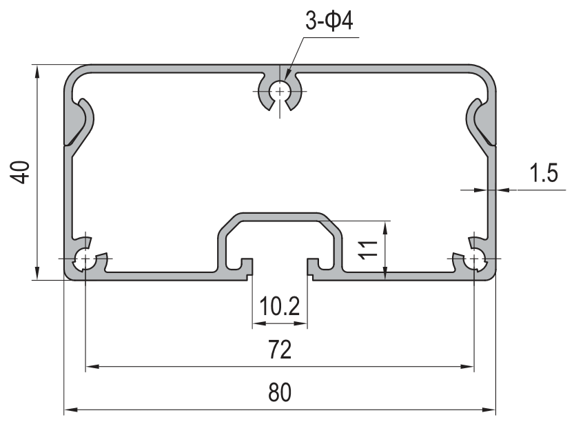
40 x 80 mm aluminium conduit profile in 6063-T5 with a 66 x 11 mm internal cavity, a 1.5 mm wall and a weight of about 1.15 kg/m. Wide enough to keep power and signal cables physically separated in one duct on a 40 series frame.
| Material | Aluminium |
|---|---|
| Alloy Grade | 6063-T5 |
| Temper | T5 |
| Section Size | 40 x 80 mm |
| Slot | Base has 3 x 4 mm mounting holes for T-slot nut fixing to a 40 series profile |
| Length | 6 m stock, cut to drawing to +/-0.5 mm |
| Tolerance | EN 755-9 / GB/T 6892, wall +/-0.15 mm |
| Surface | Mill finish / clear anodised / black anodised |
| MOQ | 800 |
| Lead Time | 18-28 days after deposit, longer for a custom divider rib die |
| Loading Port | Shanghai / Ningbo |
| Supply Ability | 500 t per month of wide conduit and duct profiles |
| Payment Terms | T/T 30% deposit + 70% before shipment | L/C at sight |
| Trade Terms | FOB | CIF | EXW |
| Certifications | ISO 9001:2015 | EN 755-9 | RoHS | REACH |
Large cable duct · 40 x 80 mm
A 40 x 80 mm aluminium conduit profile is an extruded duct with an 80 mm wide by 40 mm deep outside envelope, a 66 x 11 mm internal cavity, a wall of about 1.5 mm and a weight of about 1.15 kg/m in 6063-T5. It mounts to the slot of a 40 series profile with T-slot nuts and takes a snap or gasketed cover. The reason to use it rather than two 40 x 40 ducts is that its 66 mm of usable width lets power and signal cables share one duct while staying physically apart, which is what keeps switching noise out of a control signal. It sits at the wide end of the aluminium conduit profiles range, alongside the narrower sections used for single-service routes.
Two things decide how it is used. The first is separation: power and signal cables should not run side by side in the same air space, because a variable frequency drive or a contactor couples noise into a signal cable by induction, and the fix is distance or a grounded metal barrier rather than a thicker insulation. The second is support: a 40 x 80 duct is a long, shallow section, and a run that spans between widely spaced supports sags, which shows as a wavy cover line and eventually as a loose cover. Support it every 1.5 m as a working default, and closer where the run also carries a device.
Why power and signal cannot share the same air space
Noise gets from a power cable into a signal cable in three ways: by capacitive coupling between conductors that run close together, by inductive coupling from the magnetic field around a current-carrying cable, and by a shared return path where the two circuits use the same earth conductor. All three depend on distance, and two of the three are greatly reduced by putting a grounded metal barrier between the cables rather than by changing the cable itself.
In practice the rule is to separate power and signal by at least one cable diameter where they run parallel, and to increase that distance as the power cable gets bigger or as the current becomes switched or pulse-width modulated. Where a long parallel run is unavoidable, the barrier matters more than the distance, which is exactly what a wide duct with an internal divider is for.
| Cable type in the duct | Minimum separation | Barrier needed |
|---|---|---|
| Extra-low voltage signal, analogue | One cable diameter | Recommended for runs over 2 m |
| Digital control and encoder cable | One cable diameter | Recommended, and ground the shield at one end |
| Motor cable from a VFD | Two to three cable diameters | Yes, grounded metal barrier |
| Mains power, lighting and socket circuits | One cable diameter | Recommended |
| Safety circuit wiring | Separate duct where possible | Yes, and keep it out of the power duct |
Shielding is not a substitute for separation. A screened signal cable still couples noise if it runs alongside a motor cable for metres, because the screen carries the interference as a common-mode current. Fix the geometry first — distance or a grounded divider — and treat the screen as a second line of defence.
Four ways to make the divider
The 66 mm of usable width in this duct can be split in four ways, and the choice depends on whether the barrier has to be earthed, whether cables have to be added later, and how much width the power side needs.
Span, deflection and support spacing
A 40 x 80 duct is shallow in one direction and wide in the other, so it is much stiffer against a vertical load than its 40 mm depth suggests, and much less stiff against a side load. Cable weight is light, so deflection under the cables alone is small; the reasons to support a long run are to keep it visually straight, to stop it vibrating on a machine, and to carry any device mounted on it. The figures below are planning values for a simply supported span under a 3 kg/m cable load, with a second moment of area of about 10 cm4 and a modulus of 70 GPa.
| Support spacing | Mid-span deflection at 3 kg/m | Comment |
|---|---|---|
| 1.0 m | about 0.05 mm | Rigid, no visible sag, use where a device is mounted |
| 1.5 m | about 0.3 mm | Recommended default for a cable-only run |
| 2.0 m | about 0.9 mm | Acceptable but the cover line starts to show a wave |
| 2.5 m | about 2.1 mm | Visible sag, avoid unless the run is hidden |
| 3.0 m | about 4.3 mm | Not recommended for a visible or vibrating run |
Two things change the picture. A run that also carries a socket outlet, a junction box or a small device is no longer carrying cable weight alone, so treat it as a loaded beam and halve the spacing. A run on a machine with vibration should be supported closer than the deflection figure alone suggests, because vibration loosens a cover long before the duct visibly sags.
40 x 80 or 40 x 40
The two sizes are not alternatives; they do different jobs in the same frame. A 40 x 40 duct is a single-service route: signal wiring along a workbench, control cable inside a cabinet, or a short run to a device. A 40 x 80 duct is used where two services have to share a route, where the cable count is high, or where the duct is also a visible frame member and a single wide cover reads better than two narrow ones.
| Question | 40 x 40 duct | 40 x 80 duct |
|---|---|---|
| Cavity | 32 x 8.2 mm, about 262 mm2 | 66 x 11 mm, about 726 mm2 |
| Services | One, signal or power | Two, separated by a divider |
| Weight | about 0.62 kg/m | about 1.15 kg/m |
| Cover line on a visible frame | Narrow, needs two runs for two services | One wide cover reads as a single detail |
| Typical use | Workbench and cabinet wiring | Long frame runs with power and signal |
Where both sizes appear on the same frame, the usual arrangement is a 40 x 80 duct along the main horizontal run carrying power and signal, and 40 x 40 ducts dropping from it to the individual stations. Both mount on the same 40 series profile slot with the same T-slot fastening elements, so a mixed run needs no special parts, and covers and end caps come from the profile accessories range. Where the run is fixed to a bench or a platform, the brackets and feet come from the floor elements range, and the sections themselves are part of the wider aluminium sections we extrude.
Alloy, finish and how it is supplied
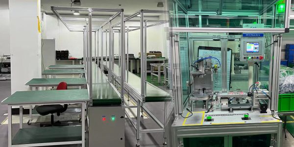
The section is extruded in 6063-T5, in mill finish, clear anodised or black anodised. Mill finish is what most industrial frames use; anodising is chosen where the duct is visible or where it sits in a washdown area and has to be wiped clean. Cutting, drilling and any divider groove machining are done before the finish is applied, so give the entry positions, the mounting holes and the divider requirement with the cut list. Coloured runs are processed as anodised aluminium profiles in one batch, and any machining is done on CNC machining centres.
Frequently asked questions
Why do power and signal cables need to be separated in one duct?
Because noise couples from a power cable into a signal cable by capacitance, by inductance and through a shared earth path, and all three depend on distance. Separate them by at least one cable diameter where they run parallel, and use a grounded metal barrier for long runs or where the power cable is fed from a VFD.
How do I make the divider inside a 40 x 80 duct?
Four ways: an extruded rib drawn into the die, a clip-in divider strip, two ducts side by side, or a grounded metal barrier. The extruded rib is the cleanest and is specified at the enquiry stage; a clip-in strip lets the split change on a later order.
How often should a long duct run be supported?
Every 1.5 m as a working default for a cable-only run. Halve that where the duct also carries a device, and support it closer on a machine with vibration, because vibration loosens a cover long before the duct visibly sags.
When should I use 40 x 80 rather than 40 x 40?
When two services have to share one route, when the cable count is high, or when the duct is also a visible frame member and one wide cover reads better than two narrow ones. A 40 x 40 duct is for a single service or a short drop to a device.
Can you supply the duct with a divider rib?
Yes, as a custom die feature, normally from about one tonne per section. Send the cable schedule and the split you need and we will confirm the rib position and whether the divider should be earthed.
Send the cable schedule and the span, not only the duct size
Tell us which services have to share the route, whether the power side is fed from a VFD, and how far the run spans between supports. We will confirm the divider arrangement, whether it should be bonded to earth, and the support spacing, then quote the extrusion, the cutting, the drilling, the divider and the finish as one package with FOB pricing, supplied with covers and end caps bagged by assembly.
Request a QuoteRelated Products
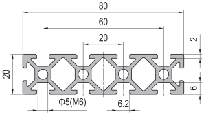 PG20 80×20 mm Ten Slot Aluminium Strut Profile Wide Flat Beam for Cable Tray and Panel Support
80 x 20 mm ten slot PG20 aluminium strut profile in 6063-T5 with a…
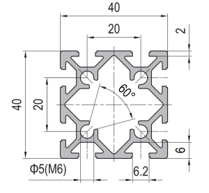 PG20 40×40 mm Eight Slot Aluminium Strut Profile 20 mm Pitch T-Slot Extrusion for Dense Fixtures
40 x 40 mm eight slot PG20 aluminium strut profile in 6063-T5 with two…
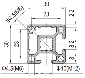 PG30 30×30 mm Two Slot Type A Aluminium Strut Profile Closed Face T-Slot Extrusion
30 x 30 mm Type A two slot PG30 aluminium strut profile in 6063-T5…
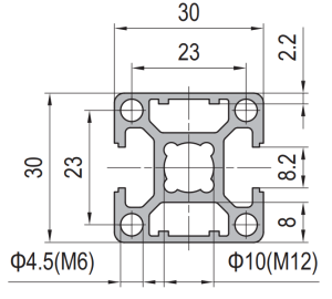 PG30 30×30 mm Two Slot Type B Aluminium Strut Profile Symmetric T-Slot Extrusion for Corner Posts
30 x 30 mm Type B two slot PG30 aluminium strut profile in 6063-T5…
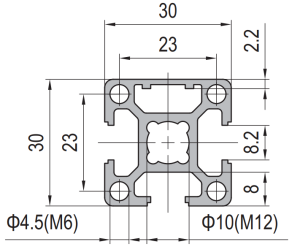 PG30 30×30 mm Three Slot Aluminium Strut Profile Light Frame Column
30 x 30 mm aluminium strut profile with three 8.2 mm T-slots and one…
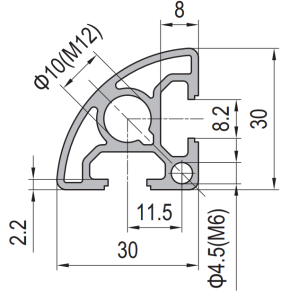 PG30 30×30 mm R90 Two Slot Aluminium Strut Profile Rounded Corner Rail
30 x 30 mm quarter round aluminium profile with one 8.2 mm T-slot on…
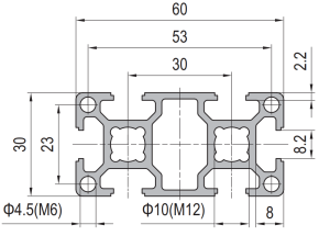 PG30 60×30 mm Six Slot Aluminium Strut Profile Rectangular T-Slot Extrusion for Cabinet Uprights
60 x 30 mm six slot PG30 rectangular aluminium strut profile in 6063-T5 with…
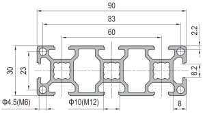 PG30 90×30 mm Eight Slot Aluminium Strut Profile Wide Beam T-Slot Extrusion for Door Frames
90 x 30 mm eight slot PG30 wide beam aluminium strut profile in 6063-T5…
