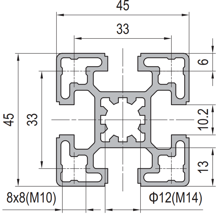
Quick answer
Fix the geometry and the size chooses itself
Halving a span is worth four times the load. Going from one 2,400 mm span to four 600 mm spans multiplies the allowable central load by sixteen. The equivalent stiffness bought by changing section is far more expensive.
Bending is the expensive load path. A frame resists load in three ways: members bend, columns and braces push, and panels shear. Bending is by far the least efficient of the three, and most frame design is spent making bending work harder than it needs to.
A diagonal in the same profile is over 300 times stiffer than a beam. That is the arithmetic behind bracing, and it is why a frame with one diagonal feels solid while the same frame without it feels like a hinge.
Put supports where the load is, not where it is tidy. Evenly spaced supports are the right answer for a distributed load and the wrong answer for a machine sitting at one end.
The principle
A frame resists load in three ways, and one of them is much worse
Every structural member in an aluminium frame is doing one of three jobs, and the difference in efficiency between them is enormous. Understanding which one you are asking a member to do explains almost every selection problem in aluminium framing.
Bending
A beam carrying a load across a gap. The material at the top of the section is compressed and the material at the bottom is stretched, and only the material near those two extremes is working hard. Most of the section is doing very little. This is the least efficient way to carry a load and it is what almost every horizontal frame member does.
Axial
A column pushing down, or a diagonal pushing or pulling along its length. Every square millimetre of the section carries the same stress, so the whole section is working. This is why a thin tube is strong in tension and why a diagonal is so effective: the material is used evenly.
Shear in a panel
A bolted-on sheet or panel acting as a diaphragm. A properly fastened panel converts sideways load into shear in the sheet, which is stiff and weighs almost nothing extra because the panel was going to be there anyway. An improperly fastened panel contributes nothing at all.
The design principle that follows is simple and worth writing on the wall: whenever you can convert a bending problem into an axial problem, do it. A diagonal brace is the cheapest such conversion available, and it is why almost every frame that feels solid has triangles in it.
The number that explains why bracing works
Take one 40 × 40 mm standard section, 1,500 mm long, and load it two different ways. As a beam with a central point load, its stiffness is 48·E·I/L³. As an axial member, its stiffness is E·A/L.
beam: 48 × 70,000 × 95,000 / 1,500³ ≈ 95 N/mmaxial: 70,000 × 650 / 1,500 ≈ 30,300 N/mmSame section, same length, same alloy. The axial stiffness is about 320 times the bending stiffness. A is the cross-sectional area, about 6.5 cm² for this section.That is the whole reason a diagonal works. It is not that a diagonal is a clever trick — it is that you are moving the load into a mode where the material is roughly three hundred times more effective. It also explains the corollary: a diagonal brace can be a much smaller section than the member it braces and still do its job, because it is not being asked to bend.
The consequence for section choice
If your frame is still moving after you have braced it and supported it sensibly, you have a genuine bending problem and the section calculation in our size selection guide will give you the answer. If you have not braced it, do not open a catalogue yet — you will buy aluminium to solve a geometry problem, and you will buy too much of it.
Supports
What each support is worth
Supports are the cheapest stiffness available in a frame, because an upright costs one short length of profile and two sets of brackets while a section upgrade costs extra weight on every metre of the frame. The table below shows the effect of dividing a 2,400 mm run with 40 × 40 mm standard wall, holding the deflection limit at L/300.
| Arrangement | Span each | Allowable central load per span | Gain over one span | Added weight |
|---|---|---|---|---|
| One span, no support | 2,400 mm | 19 kg | 1× | none |
| Two spans, one mid-support | 1,200 mm | 75 kg | 4× | about 1.5 kg |
| Three spans, two supports | 800 mm | 169 kg | 9× | about 3.1 kg |
| Four spans, three supports | 600 mm | 301 kg | 16× | about 4.6 kg |
| One span in 50 × 100 on edge, no support | 2,400 mm | 297 kg | 16× | about 10.8 kg |
Look at the last two rows together, because they are the punchline of this article. Three extra uprights in the smallest section in the range give the same allowable load as stepping all the way up to a 50 × 100 rectangular section used on edge — and they weigh less than half as much. The section upgrade has no other benefit to offer; the uprights also stiffen the frame in the sideways direction and give you something to mount to.
The constraint that decides it
Supports are cheaper than sections, but they are not free in every sense. An upright takes floor space, blocks access, has to be levelled, and in some machines cannot go where you want it. If the middle of a machine base has to stay clear for a conveyor or a robot, the calculation above is academic and the larger section is the correct answer. Decide the access constraint first, then do the arithmetic inside it.
Where to put the supports
Evenly spaced supports are the standard answer and they are the right answer for one specific case: a load that is spread evenly along the whole member. For everything else, put the support under the load.
- A heavy component at one end. Put the support under the component. Moving it to the middle of the member leaves a short heavily loaded span at one end, which is the worst of both worlds.
- Two components at unknown future positions. Use three equal spans. That arrangement keeps the worst-case deflection low wherever the loads end up, and it is the most forgiving layout for a frame whose contents will change.
- A long conveyor run. Space the supports by the deflection limit rather than by the frame module. Work backwards from the allowable span for the load you expect, then round down to a spacing that matches your panel or guarding module.
- A member that also has to resist a sideways push. The support must be braced in that direction too, or it simply moves sideways and does nothing for the load.
The fourth thing that is not a support
Four things that look like supports and are not
Most frames that “need a bigger profile” are actually relying on one of these four things to act as a support or a restraint. None of them does.
An unbraced mid-upright
An upright that is free to move sideways under load is a pin, not a support. It will hold the beam up under a purely vertical load and then lean as soon as anything pushes the frame. If a mid-support is doing structural work, brace it in both horizontal directions.
A two-bolt corner bracket
A corner bracket with two bolts resists rotation by friction and bolt bearing only. Its moment capacity is proportional to the distance between the bolts, which on a standard bracket is small. If a corner has to carry moment, use a flat joining plate or a gusset that puts the fixings further apart.
A castor or a levelling foot
A castor or a ball foot is a pin. A frame on castors has no rotational restraint at the base, which is why mobile benches feel less rigid than the same bench on bolted feet. Levelling feet with a locking nut are better than castors, and bolting down is better still.
A panel fixed with four bolts
A panel contributes to the frame only if it is fastened closely enough around its perimeter for shear to transfer into it. Four bolts in the corners of a 1,000 mm panel make a very flexible connection. Panels that are doing structural work need fasteners at a spacing the panel itself can carry, not just at the corners.

Worked comparison
A 2,400 mm rail, four ways to carry the same load
A sensor gantry rail has to carry 250 kg at mid-length over a 2,400 mm opening, with a deflection limit of L/300 — that is 8 mm. Four layouts can do it. Here is what each one costs in aluminium.
| Layout | Section | Supports | Allowable load | Profile weight |
|---|---|---|---|---|
| A. Single span | 40 × 40 standard | none | 19 kg — fails | 4.1 kg |
| B. Single span, rectangular | 50 × 100 on edge | none | 297 kg — passes | 14.9 kg |
| C. Three spans | 40 × 40 standard | 2 uprights at 800 mm | 169 kg — fails | 4.1 kg plus 3.1 kg of upright |
| D. Four spans | 40 × 40 standard | 3 uprights at 600 mm | 301 kg — passes | 4.1 kg plus 4.6 kg of upright |
Layout B and layout D both pass, and they are not comparable on cost. B uses 14.9 kg of 50 × 100 section, needs brackets sized for a 50 series slot with an M10 nut at a 30 N·m torque figure, and occupies 100 mm of depth. D uses 8.7 kg of 40 × 40, keeps the whole frame in one accessory system, and adds three uprights that also brace the gantry sideways.
Layout C is the interesting one, because it is the layout most people would choose. Two uprights at the third points looks tidy and is the correct spacing for a distributed load, but this load is concentrated at mid-length and a third point support leaves a 800 mm span with the load in the middle of it. Layout D is only one extra upright and it clears the requirement by a factor of 1.2.
The general rule this illustrates
Place the supports where the load is. A gantry with a load at mid-length wants a support at mid-length, or enough supports that no span has the load near its centre. Even spacing is a good default for spread loads and a poor default for concentrated ones.
Before the catalogue
Six questions to answer before you choose a section
Work through these six in order and you will usually find that the section is determined before you reach the end. Skipping the first five is what produces the frames that get re-specified twice.
A one-line sanity check
Allowable central point load in kilograms is roughly 1.14 × 10⁷ × I in cm⁴ divided by the span in millimetres squared, working to L/300 with 6063-T5. Use it to check any load figure a supplier gives you, and to check your own design before you send it out.
Questions
Frequently asked questions
Should I add a support or buy a bigger profile?
Add the support, unless an access constraint prevents it. Halving a span gives four times the allowable load at the same deflection limit, and an upright plus two sets of brackets is a fraction of the weight of upgrading every metre of the frame. On a 2,400 mm run, three extra 40 × 40 uprights weigh about 4.6 kg and give the same load capacity as a 50 × 100 section on edge that weighs 10.8 kg more.
Where should a mid-support go?
Under the load. Even spacing is the right answer for a uniformly distributed load and the wrong answer for a concentrated one, because it leaves the load in the middle of a span rather than at a support. If you do not know where the load will be, use three equal spans, which is the most forgiving arrangement for a frame whose contents may change.
Does a diagonal brace really make a frame stiffer?
Yes, and by a very large margin. A 40 × 40 mm section 1,500 mm long has an axial stiffness of about 30,300 N/mm and a bending stiffness of about 95 N/mm under a central point load. That is a factor of roughly 320, which is why a diagonal can be a much smaller section than the members it braces and still stop the frame moving.
How many supports does a conveyor rail need?
Space them from the deflection limit rather than from the frame module. Work out the allowable span for the load you expect at your chosen limit, then round down to a spacing that matches your panel or guarding module. On a 40 × 40 standard rail with a light distributed load, support spacings of 1,000 to 1,500 mm are typical; past 1,500 mm the rail sags enough that belt tracking starts to suffer.
Is a longer span always worse?
For deflection, yes, and sharply: deflection rises with the cube of the span, so doubling a span cuts the allowable load to about a quarter at a constant deflection limit. For yield strength the effect is much gentler, and below roughly a metre of span the strength limit governs instead. That is why short, heavily loaded members fail by yielding while long, lightly loaded ones simply sag.
Can I use the machine panel as a structural element?
Yes, if it is fastened closely enough around its perimeter for shear to transfer into it. A panel fixed with four bolts in the corners of a 1,000 mm frame is not a diaphragm and contributes almost nothing. A panel with fasteners at a spacing the sheet can carry becomes a very cheap shear element and can remove the need for diagonal bracing entirely. Check with the panel supplier what spacing their sheet can span.
Send us the layout and we will check the geometry
Send the frame drawing or a sketch with the load positions, and we will tell you where the supports should go and which section the remaining spans actually need.
Related reading
Twelve more engineering notes from this blog, picked for this article — plus every category below.
 Engineering Design3030 vs 4040 Aluminium Profile: Which for Your Frame
 Engineering DesignExtruded vs Cast Aluminium: Stronger in One Direction, Not in All of Them
 ApplicationsAluminium Profile Applications
 Applications40×40 Aluminium Profile: Where It Works, Where It Fails, and Why
 Engineering DesignAluminium Extrusion Die Cost (2026): Price by Section Size
 Engineering DesignAluminium Extrusion Lead Time: New Die vs Existing Die
 Engineering DesignCut-to-Length, Drilling and Tapping: What Fabrication Adds
 Engineering Design4080 vs 4545 Aluminium Profile: Which for Your Frame
 Sourcing and ProcurementAluminium Profile Quote: What Changes the Number by Quantity
 Sourcing and ProcurementFOB vs CIF vs DAP vs DDP: Aluminium Profile Landed Cost
 Sourcing and ProcurementAluminium Profile MOQ: 150 m Existing Die, 500 m New
 Quality and InspectionT-Slot Aluminium Profiles for Industrial Frames and Automation: A Specification Playbook
