Section comparison · 30 against 40
3030 vs 4040 Aluminium Profile: A Decision With Numbers
The usual answer is that a 4040 is “more than twice as strong”. It is 2.6 times as stiff, 1.35 times as heavy, and it buys bending stiffness at roughly half the cost per unit. It also commits you to a different fixing class. Here is the whole comparison, with the arithmetic that decides it.
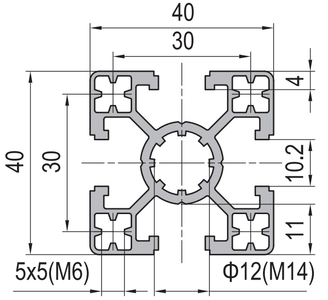
Quick answer
- Stiffness ratio 2.6, weight ratio 1.35. A 40 × 40 standard has about 9.2 cm4 of second moment of area against about 3.6 cm4 for a 30 × 30 standard, at 1.75 kg/m against 1.30 kg/m.
- Per unit of stiffness, the 4040 is about 47 per cent cheaper. Divide weight by inertia and the 4040 comes out at roughly half the cost per cm4 per metre. If you need stiffness, the bigger section is the cheaper way to buy it.
- At 1,000 mm the difference is 41 kg against 105 kg. Those are the allowable mid-span point loads at a span/300 deflection limit. Below about 500 mm the two are close enough that the joint, not the section, decides.
- The fixing class is a bigger commitment than the size. A 30 series slot takes M5 and M6 class nuts; a 40 series slot takes M6 and M8. The torque ceiling roughly doubles, and the accessory catalogue is far larger in the 40 series.
- 3030 wins when you do not need the stiffness. Short spans, lightly loaded enclosures, frames whose job is to hold a panel rather than carry a load, and any design where the extra 0.45 kg/m multiplied by the total length is real money.
- 4040 wins when the span is real. Anything above about 800 mm carrying a load, any moving axis, any frame that has to hold position under a varying force.
Also searched as 30x30 vs 40x40 aluminium profile, 3030 vs 4040 aluminium extrusion, which aluminium profile is stronger, 3030 and 4040 load capacity, aluminium profile size comparison, T-slot profile selection.
The two sections, side by side
Both are standard-wall four-slot sections in 6063-T5. Neither is a special. They are the two most common framing members in the market, and they differ in more ways than the envelope.
| Property | 30 × 30 standard | 40 × 40 standard | Ratio |
|---|---|---|---|
| Envelope | 30 × 30 mm | 40 × 40 mm | 1.33 |
| Wall thickness | about 1.8 mm | about 2.0 mm | 1.11 |
| Weight | 1.30 kg/m | 1.75 kg/m | 1.35 |
| Second moment of area | 3.6 cm4 | 9.2 cm4 | 2.56 |
| Section modulus | about 2,400 mm3 | about 4,600 mm3 | 1.92 |
| Stiffness per kg/m | 2.8 | 5.3 | 1.89 |
| Slot mouth | 6 – 8 mm | 8 mm | – |
| Fixing class | M5, M6 | M6, M8 | – |
| Typical torque ceiling | about 6 N·m | about 15 N·m | 2.5 |
| Slot pitch | 22 – 24 mm | 30 mm | 1.3 |
| Centre bore | ⌀6.8 mm, taps M6 | ⌀8.2 mm, taps M14 | – |
| Allowable point load at 1,000 mm | 41 kg | 105 kg | 2.56 |
Look at the two ratio columns. The weight ratio is 1.35. The inertia ratio is 2.56. The section modulus ratio — which governs yielding rather than deflection — is only 1.92, because the section modulus scales with the depth rather than with the cube of it.
Head to head
Bar length is proportional to the larger of the two figures, so the 4040 is always the full-length bar.
Light pink is the 30 × 30 standard, dark red is the 40 × 40 standard. The top pair is the argument for the bigger section. The bottom pair is the argument against the smaller one: per unit of stiffness, the 3030 costs nearly twice as much material to do the same job.
That last figure explains a lot of confused conversations. If a joint or a bracket is the limiting feature, the relevant number is the section modulus, and the gain from going up a size is under 2 times. If the member is bending over a span, the relevant number is the inertia, and the gain is 2.6 times. Most machine frames are in the second case, which is why the 4040 feels like a much bigger jump than the dimensions suggest.
The number that actually decides the purchase
Stiffness comparisons in isolation are not a purchasing decision. The decision is how much stiffness you get for the money, and the honest way to compare two sections is to divide cost by stiffness. Delivered cost per metre tracks mass closely for sections of the same alloy and finish, so mass is a fair stand-in for cost in this comparison.
Cost per unit of bending stiffness
Cost index = weight per metre ÷ second moment of areaLower is better. This is the number of kilograms you pay per cm4 of inertia, per metre of member. It answers the question “if I need a given stiffness, which section gets me there for least material?”
| Section | Weight (kg/m) | I (cm4) | Cost index | Relative |
|---|---|---|---|---|
| 30 × 30 light | 0.95 | 2.6 | 0.365 | 192% |
| 30 × 30 standard | 1.30 | 3.6 | 0.361 | 190% |
| 40 × 40 light | 1.30 | 6.1 | 0.213 | 112% |
| 40 × 40 standard | 1.75 | 9.2 | 0.190 | 100% |
| 40 × 40 heavy | 2.35 | 12.4 | 0.190 | 100% |
| 45 × 45 standard | 2.55 | 15.5 | 0.165 | 87% |
This is the table that changes the conversation. Going from a 30 × 30 standard to a 40 × 40 standard takes the cost index from 0.361 to 0.190 — the 4040 delivers stiffness at 53 per cent of the cost per unit. If the design needs stiffness, the 3030 is not the economical choice, it is the expensive one, because you are paying for a section that cannot do the job and then adding supports to compensate.
Note too that the cost index is flat across the 40 series wall grades. Light, standard and heavy wall all land at roughly the same value. That is a useful result: within a series, the wall grade is a near-neutral choice on cost per unit stiffness, so you should pick the wall grade by what else you need — the bore size, the thread depth, the slot lip strength — rather than by stiffness economics.
The one-line version
If you need stiffness, buy a bigger section. If you need material out of the design, buy a smaller one. The mistake is buying a smaller section and then adding members to make it stiff, which pays the cost twice.
What the stiffness difference looks like at real spans
The deflection of a simply supported member with a mid-span point load is:
Mid-span deflection
δ = F × L3 ÷ (48 × E × I)F in newtons, L in mm, E = 70,000 N/mm2 for 6063 in any temper, I in mm4. Convert I from cm4 by multiplying by 10,000.
Put a 50 kg load at mid-span and vary the span. The table below shows the deflection in millimetres, with the span/300 limit for comparison. Where the deflection exceeds the limit, the section is not usable at that span for that load.
| Span | 30 × 30 standard | L/300 limit | 40 × 40 standard | L/300 limit |
|---|---|---|---|---|
| 500 mm | 0.51 mm | 1.67 mm | 0.20 mm | 1.67 mm |
| 750 mm | 1.71 mm | 2.50 mm | 0.67 mm | 2.50 mm |
| 1,000 mm | 4.05 mm | 3.33 mm | 1.59 mm | 3.33 mm |
| 1,250 mm | 7.91 mm | 4.17 mm | 3.10 mm | 4.17 mm |
| 1,500 mm | 13.67 mm | 5.00 mm | 5.35 mm | 5.00 mm |
| 2,000 mm | 32.4 mm | 6.67 mm | 12.68 mm | 6.67 mm |
Read the bold transition points. The 30 × 30 standard crosses its span/300 limit somewhere between 750 and 1,000 mm under a 50 kg load. The 40 × 40 standard crosses its limit between 1,250 and 1,500 mm. So for a 50 kg mid-span load the usable span roughly doubles, which is the practical form of the 2.6 times stiffness ratio.
Now read the 500 mm row. Both sections are comfortably inside the limit and the absolute deflections are a fraction of a millimetre. At that span, the section is not the constraint at all — the joint is. A 30 series bracket with M5 bolts at 6 N·m will let go, or slip, long before either section bends measurably. This is the case that the “bigger is stronger” reflex gets wrong, and it is more common than the industry admits.
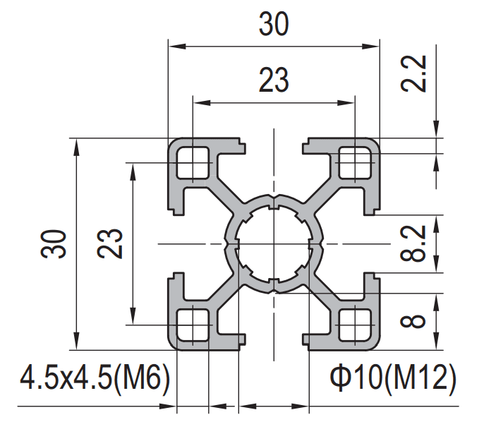
The fixing class is the bigger commitment
Buyers focus on the envelope because it is visible, and then discover that the real constraint is the hardware. The slot geometry decides which nuts fit, which brackets fit, how much torque a joint will take, and how much of the accessory catalogue is available to you.
The compact fixing system
- Slot mouth 6 to 8 mm, taking M5 and M6 class nuts
- Torque ceiling around 6 N·m
- Slot pitch 22 to 24 mm, so brackets are smaller and closer together
- Centre bore about 6.8 mm, tapping M6
- Accessory range is narrower — fewer hinges, fewer heavy brackets, fewer feet
The default system
- Slot mouth 8 mm, taking M6 and M8 class nuts
- Torque ceiling around 15 N·m
- Slot pitch 30 mm, so brackets sit further apart and carry more moment
- Centre bore about 8.2 mm, tapping M14
- Largest accessory range in the market — everything is dimensioned around it
Two consequences follow that have nothing to do with deflection.
First, the joint capacity roughly doubles with the section. The torque ceiling goes from about 6 to about 15 N·m, and the bolt spacing goes from 22 to 30 mm. A joint’s moment capacity is the bolt force times the lever arm, so the 40 series joint carries more than twice the moment of the 30 series joint. On a short-span frame where the section is not the constraint, this is the entire argument for the bigger size.
Second, the accessory catalogue is not proportional. It is lopsided. The 40 series has hinges, handles, castors, levelling feet, cable ducts, panel fixings, linear rails and dozens of bracket variants, because it is the volume product. The 30 series has a workable but much thinner range. If your design needs a hinge and a castor and a panel fixing, the 40 series will save you weeks of custom bracket design that has nothing to do with the load calculation.
The cross-series mistake
A 30 series and a 40 series look similar enough on a photograph that people try to mix them. They do not mix. The slot mouths are different, the pitches are different and the bolts will not seat on the slot axis. A frame that starts in 30 series and grows into 40 series will need adapter plates at every transition, and those plates are usually more expensive than the material saving that prompted the mix.
Moving mass: where the lighter section genuinely wins
The strongest argument for the 30 series is not cost, it is mass in motion. If the member moves — a gantry beam, a travelling carriage, a lifting frame — its own weight has to be accelerated and decelerated on every cycle, and it also has to carry itself over whatever span it crosses.
Take a 2 m gantry beam carrying a 20 kg tool head, driven at 1 m/s2. The moving mass includes the beam.
| Item | 30 × 30 standard | 40 × 40 standard |
|---|---|---|
| Beam mass, 2 m | 2.60 kg | 3.50 kg |
| Tool head mass | 20.0 kg | 20.0 kg |
| Total moving mass | 22.6 kg | 23.5 kg |
| Accelerating force at 1 m/s2 | 22.6 N | 23.5 N |
| Beam self-weight deflection at 2,000 mm | 1.05 mm | 0.56 mm |
The result is worth stating plainly because it contradicts the usual assumption. The extra 0.9 kg of beam adds about 4 per cent to the moving mass and about 4 per cent to the drive force. On a short beam with a significant payload, the mass argument is nearly irrelevant to the drive sizing.
Where it does matter is the last row. The beam has to carry its own weight across the span, and self-weight deflection under a distributed load goes with the fourth power of span. At 2 m the 3030 sags 1.05 mm under nothing but itself, roughly twice the 4040. Extend the beam to 3 m and both get much worse, but the 3030 gets worse faster because it starts from a lower inertia. On a long moving axis, the section choice is being made by self-weight, not by the payload.
There is a third mass effect that only shows up in dynamics: a lighter beam has a higher natural frequency, so a servo axis can be tuned more aggressively before it excites a resonance. If the application is a fast pick-and-place axis with a short stroke, that can be the deciding factor and it favours the lighter section outright.
The decision, in order
Work through these in sequence. Each one either settles the question or narrows it.
- What is the unsupported span? Below about 500 mm, both sections are stiff enough for most loads and the decision is made by the joint and the accessories. Above about 800 mm, the load calculation starts to govern.
- What is the mid-span load, and what deflection can the application tolerate? Use the span/300 table. If a 50 kg load at your span puts the 3030 over the limit and the 4040 under it, the decision is made and there is nothing further to discuss.
- Is the member static or moving? Static and stiffness-limited, go up a size. Moving with a short stroke and a light payload, the lower mass can be worth more than the extra stiffness, and the 30 series becomes competitive.
- What does the joint have to carry? If the joint moment is the governing case, the 40 series wins on torque ceiling and bolt spacing regardless of the deflection numbers.
- What accessories does the design need? If it needs hinges, castors, heavy feet, panel fixings or a linear rail, the 40 series catalogue answers all of them and the 30 series catalogue does not.
- What is the total length in the bill of materials? This is the last check, not the first. Multiply the 0.45 kg/m difference by the total metres. If that is a meaningful number and the design passes steps one to five on the 3030, take the saving.
Run in that order, the answer is usually unambiguous. Run in the reverse order — starting from price — and you end up with a 3030 frame, an undersized section, a set of adapter plates and a support structure that costs more than the 4040 would have.
Frequently asked questions
Is a 4040 aluminium profile twice as strong as a 3030?
How much heavier is a 4040 than a 3030?
Can I use 3030 brackets on a 4040 profile?
What is the maximum span for a 3030 aluminium profile?
Which is better for a moving gantry, 3030 or 4040?
Does going up a wall thickness help as much as going up a size?
Give us the span and the load
We supply the 30 and 40 series in light, standard and heavy wall, cut to length and machined, with the matching brackets and slot hardware. Send us the span, the load and the deflection you can live with, and we will tell you which section holds it — including when the answer is the cheaper one.
Related reading
Twelve more engineering notes from this blog, picked for this article — plus every category below.
 Engineering DesignAluminium Extrusion Die Cost (2026): Price by Section Size
 ApplicationsHow to Fix Panels, Guards and Accessories to Aluminium Profiles
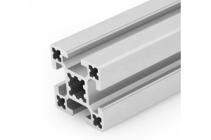 Engineering DesignT-Slot vs V-Slot Aluminium Profiles: The V Is a Raceway, Not a Cheaper T
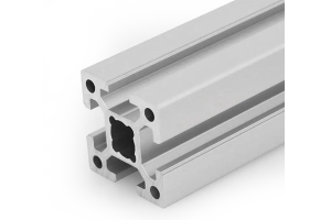 Engineering Design3030 vs 4040 Aluminium Profile: Which for Your Frame
 Engineering DesignAluminium Extrusion Capacity: What a Factory Can Actually Deliver
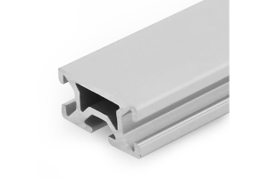 Engineering DesignMetric vs Imperial T-Slot Profiles: How to Test Compatibility Before You Order
 Engineering DesignExtruded vs Cast Aluminium: Stronger in One Direction, Not in All of Them
- Engineering DesignWhat Is a 3030 Aluminium Profile? (Weight, Slot and Load)
 Sourcing and ProcurementImporting Aluminum Profiles from China: Nine Failures That Quietly Raise Your Landed Cost
 Sourcing and ProcurementAluminium Profile Quote: What Changes the Number by Quantity
 ApplicationsCleanroom and Medical Framing: There Is No Medical-Grade Aluminium Extrusion
 Quality and InspectionT-Slot Aluminium Profiles for Industrial Frames and Automation: A Specification Playbook
