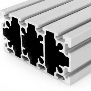
PG45 180 x 90 mm Twelve Slot Aluminium Strut Profile Heavy Duty Column
A 180 x 90 mm twelve slot PG45 aluminium strut profile at about 9.50 kg/m with M10 hardware. As a column it is limited by buckling about the weak axis; as a beam it bends about the strong axis.
| Material | Aluminium |
|---|---|
| Alloy Grade | 6063-T5 |
| Temper | T5 |
| Section Size | 180 x 90 mm |
| Slot | 12 x 10 mm groove (45 series), M10 hardware |
| Length | 6 m stock, cut to drawing to +/-0.5 mm |
| Tolerance | EN 755-9 / GB/T 6892, wall +/-0.15 mm |
| Surface | Mill finish / clear anodised / black anodised |
| MOQ | 150 m |
| Lead Time | Typically 22 to 32 days after deposit for mill finish |
| Loading Port | Shanghai, Ningbo, Qingdao |
| Supply Ability | Extrusion, cutting, machining and anodising in house |
| Payment Terms | T/T 30 per cent deposit, balance against copy of bill of lading; L/C at sight for larger orders |
| Trade Terms | FOB, CIF, CFR, EXW |
| Certifications | ISO 9001:2015, EN 755-9, RoHS and REACH declarations |
01What is the 180 x 90 mm twelve slot profile?
What is it for?
The heavy end of the 45 series: machine gantry uprights and beams, press columns, large enclosure posts, and structures that need both a heavy section and M10 hardware. At about 9.50 kg/m a 6 m bar weighs roughly 57 kg, so it is a lifting job, not a carrying job.
Why does it take M10?
Because the 45 series groove is 10 mm against the 8 mm of the 40 series, and the section is big enough that M8 would be the limiting part. M10 gives a meaningfully higher clamping force and a bigger bolt shank in shear, which is what a joint on a 9.50 kg/m member needs.
What decides how it should be oriented?
Whether it is a column or a beam. As a beam it goes on edge, 180 mm deep, and bends about its strong axis. As a column it stands upright and is limited by buckling about its weak axis. Those two numbers are very different, and they are the whole design decision.
02Section data
| Item | Value | Note |
|---|---|---|
| Envelope | 180 x 90 mm | heavy rectangular section |
| Slots | 12 | 10 mm groove, 45 series |
| Slot pitch | 45 mm | the 45 series module |
| Fastener | M10 | 45 series slot nuts |
| Second moment, strong axis | approx. 1,477 cm4 | 180 mm deep |
| Second moment, weak axis | approx. 486 cm4 | 90 mm deep |
| Section modulus, strong axis | approx. 164 cm3 | governs beam capacity |
| Section modulus, weak axis | approx. 108 cm3 | governs column eccentricity |
| Cross-section area | approx. 3,519 mm2 | from the published weight |
| Weight | approx. 9.50 kg/m | a 6 m bar is about 57 kg |
| Alloy | 6063-T5 | EN AW-6063 |
| Length | 6 m stock | cut to drawing to +/-0.5 mm |
The two second moments differ by a factor of about three, but the two section moduli differ by only about 1.5. That is because rotating the section changes the depth as well as the distribution, and the modulus is measured against the depth. Keep the two straight: stiffness is one number, strength is another.
03As a beam: on edge, 180 mm deep
Used as a beam the member goes on edge so the 180 mm dimension is vertical. The strong axis second moment is around 1,477 cm4 and the section modulus about 164 cm3.
Against a conservative allowable stress for 6063-T5 with a safety factor of three, that gives a working bending moment in the region of 5,400 N.m. On a simply supported member carrying a uniform load, the working figures below follow.
| Span | Working uniform load | Comment |
|---|---|---|
| 1.5 m | about 1,960 kg/m | well inside the section’s capability |
| 2.0 m | about 1,100 kg/m | a normal working span for a gantry beam |
| 3.0 m | about 490 kg/m | usable, deflection becomes the check |
| 4.0 m | about 275 kg/m | deflection governs, check it against your limit |
| 5.0 m and above | not recommended as a beam | step up or add a stay |
Those figures are approximate and are for bending about the strong axis with the load on the centreline. An off-centre load on a beam this wide also twists it, and twist is usually the governing case before bending is. Send the span, the load and its offset and we will run it against the die drawing.
04As a column: upright, and limited by the weak axis
Used as a column the calculation changes completely. A column does not fail by yielding; it fails by buckling, and it buckles about its weakest axis regardless of which way you face the wide side.
The weak axis second moment here is about 486 cm4. The Euler buckling load falls with the square of the length, so a short column is limited by the material and a long column is limited by its own slenderness.
For this section the crossover sits at roughly 5 m. Below that, the working axial load is governed by the material, at around 129 kN with a safety factor of three on yield. Above it, buckling takes over and the capacity falls away quickly.
| Column length | Governing case | Working axial load |
|---|---|---|
| 2 m | material, yield | about 129 kN |
| 3 m | material, yield | about 129 kN |
| 4 m | material, yield | about 129 kN |
| 5 m | crossover | about 130 kN, buckling now governs |
| 6 m | buckling about the weak axis | about 93 kN |
| Above 6 m | buckling | falls with the square of the length |
Two things follow. Short columns are enormously strong and a 180 x 90 member used as a 2 m upright has far more capacity than most frames will ever ask of it. And length is what kills a column: doubling the length quarters the buckling capacity, which is why a tall gantry upright needs a mid-height brace far more than it needs a bigger section.
The practical rule: if the upright is over about 4 m, plan a mid-height restraint tied back to the frame. It is cheaper than stepping up a section and it raises the capacity by roughly four times.
05Column or beam: settling it
Use it as a column
- The member stands upright and carries compression
- It is part of a portal or gantry upright
- It is restrained at the top and bottom by the frame
- Length is under about 4 m, or there is a mid-height restraint
- The load is axial, or close to it
- Buckling about the weak axis is the check to do
Use it as a beam
- The member runs horizontally and carries bending
- It is a gantry cross beam or a press beam
- It is simply supported at both ends
- The span is under about 3 m
- The load is on or near the centreline
- Bending about the strong axis, plus a twist check
The awkward case is a member that does both: a gantry upright that also carries a bracket, or a beam with an axial load from a brace. Then you check both and the combination usually governs. Send the arrangement and we will run it.
06Why M10 matters on a section this size
| Aspect | M8, 40 series | M10, 45 series |
|---|---|---|
| Nominal diameter | 8 mm | 10 mm |
| Typical working torque | about 15 to 20 N.m | about 30 to 40 N.m |
| Relative clamping force | 1x | roughly 1.8x |
| Shank area in shear | 50 mm2 | 78 mm2 |
| Where it is used | 40 series frames up to 80 x 80 | 45 series heavy members like this one |
The point of the table is not that M10 is bigger. It is that a joint on a 9.50 kg/m member is carrying real load, and the fixing has to be sized for the member rather than for the convenience of a shared accessory bin. Mixing 40 series brackets onto a 45 series heavy member is the classic way a gantry joint gets under-built.
Torque figures are approximate and are for a steel nut against clean aluminium lips. Take the final figure from the nut supplier and verify it on a sample joint.
07Failure modes to design out
| What goes wrong | Why it happens | Design it out by |
|---|---|---|
| Tall upright bows sideways | buckling about the weak axis, not lack of strength | add a mid-height restraint tied back to the frame |
| Beam twists under an off-centre load | the load sits outside the outermost groove | keep loads inboard, or add a stay |
| Joint works loose | 40 series M8 brackets were used on a 45 series heavy member | use M10 45 series hardware throughout |
| Bar arrives with a set in it | it was lifted at one point: a 6 m bar is about 57 kg | lift at two points, store flat on continuous bearers |
| Slot lips deform | an M10 was tightened to a steel figure in aluminium lips | torque to the aluminium figure and verify on a sample joint |
08What to check before you order
Procurement checklist for the 180 x 90 mm twelve slot section
- Confirm the series: 45 series is a 10 mm groove on a 45 mm pitch with M10 hardware.
- Confirm whether the member is a column or a beam, and its length or span.
- Confirm whether a mid-height restraint is needed for an upright over about 4 m.
- Confirm the handling plan: a 6 m bar is about 57 kg and needs lifting gear.
- Confirm the hardware is 45 series M10, not 40 series M8.
- Confirm the cut list with end machining and any hole pattern.
- Confirm the finish and the quantity in metres.
09Terms used on this page
- Buckling
- The sudden sideways failure of a slender member in compression. It is governed by stiffness and length, not by strength.
- Slenderness
- Effective length divided by the radius of gyration. It sets how close a column is to its Euler buckling load.
- Mid-height restraint
- A brace partway up a column that halves its effective length and roughly quadruples its buckling capacity.
- Strong axis
- The axis about which a section has its larger second moment of area. Beams bend about it.
- Weak axis
- The axis about which a section has its smaller second moment. Columns buckle about it.
- Clamping force
- The compressive force a tightened bolt puts across a joint. It sets how much load the joint can transfer by friction.
10Questions buyers ask
Can it be used both as a column and as a beam?
Yes, and that is what makes it useful, but the capacities are very different. As a 2 m beam on edge the working uniform load is around 1,100 kg per metre; as a 2 m column the working axial load is about 129 kN.
What is the weight per metre?
Approximately 9.50 kg/m, so a 6 m stock length is about 57 kg and needs lifting gear.
Why M10 and not M8?
The 45 series groove is 10 mm and the section is heavy. M10 gives roughly 1.8 times the clamping force of M8 and a larger shank in shear, which is what a joint on this member needs.
How tall can an upright be?
Up to about 4 m without a mid-height restraint. Above that, plan a restraint: buckling capacity falls with the square of the length.
Is 45 series compatible with 40 series?
No. The mouth is 10 mm against 8 mm and the pitch is 45 mm against 40 mm, so the slot nuts and brackets do not interchange.
Can it be supplied cut and machined?
Yes. Send the cut list with the end machining and any hole pattern and the lengths arrive ready to assemble.
What we need to quote this section
- The section reference and the series, stated explicitly.
- Whether the member is a column or a beam.
- The length or span, and whether a mid-height restraint is part of the design.
- The load, and where it sits relative to the centreline.
- The cut list with end machining and any hole pattern.
- The finish and the quantity in metres.
Quotations are broken out into extrusion, cutting, machining, finish and hardware, so you can see which step is driving the cost on a heavy member. Browse the full aluminium profile catalogue and the 45 series aluminium profiles range for related sections.
Designing a gantry with 45 series heavy members?
Send the arrangement, the loads and the lengths. We will confirm column against beam capacity and whether a restraint is needed.
Request a quotationRelated Products
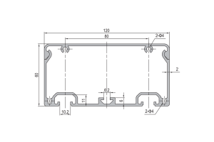 Aluminium Conduit Profile 120×60 mm Cable Duct Extrusion 2 mm Wall for Machine Wiring
120 x 60 mm aluminium conduit profile duct in 6063-T5 with a 2 mm…
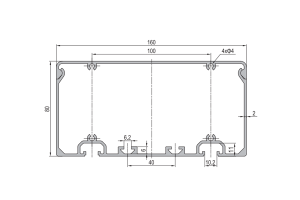 Aluminium Conduit Profile 160×80 mm Cable Duct Extrusion with Two Sided Mounting for Machine Frames
160 x 80 mm aluminium conduit profile duct in 6063-T5 with a 2 mm…
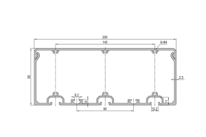 Aluminium Conduit Profile 200×80 mm Cable Duct Extrusion 2.5 mm Wall for Long Production Line Runs
200 x 80 mm aluminium conduit profile duct in 6063-T5 with a 2.5 mm…
 Agricultural Framework Aluminium Profile System 45×45 mm T-Slot for Shelving and Storage Racks
A bolted 45 x 45 mm T-slot aluminium profile framing system for agricultural shelving,…
 Assembly Line Workstation Aluminium Profile Frame 40×40 mm T-Slot Workbench Structure
A re-configurable assembly workstation frame in 40 x 40 mm T-slot aluminium profile with…
 Conveyor System Aluminium Profile Extrusion Frame 45×60 mm for Belt and Roller Lines
A bolted conveyor frame in 45 x 60 mm T-slot aluminium profile with 45…
 Cubic Connector 4545 45x45x45 mm Three-Way Aluminium Corner Joint Block for 45 Series
A 45 x 45 x 45 mm three-way cubic corner connector for 45 series…
 PG20 60 x 20 mm Eight Slot Aluminium Strut Profile Wide Miniature Rail
60 x 20 mm eight-slot aluminium strut profile with 6.2 mm grooves on a…
