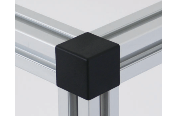
Aluminium Cubic Connector 2020 20×20 mm Three-Way Corner Joint with ABS Cap
A 20 x 20 x 20 mm three-way cubic corner connector for 20 series aluminium profiles, with a counterbored bore on each face and a clip-on black ABS cap.
| Material | Zinc alloy die casting with ABS cap |
|---|---|
| Alloy Grade | Zamak 3 die casting, ABS cap |
| Temper | custom |
| Section Size | 20 x 20 x 20 mm cube, suits 20 mm profile faces |
| Slot | Suits 20 series 6.2 mm groove profiles |
| Length | Stocked, no cutting required |
| Tolerance | ISO 8062 die casting | ISO 2768-m machining |
| Surface | Natural die casting finish |
| MOQ | 500 |
| Lead Time | 15-25 days after deposit |
| Loading Port | Shanghai / Ningbo |
| Supply Ability | 800,000 pieces per month |
| Payment Terms | T/T 30% deposit + 70% before shipment | L/C at sight |
| Trade Terms | FOB | CIF | EXW |
| Certifications | ISO 9001:2015 | RoHS | REACH |
Connecting elements · Cubic corner joints
A cubic connector 2020 is a 20 x 20 x 20 mm three-way corner block for 20 series aluminium profiles. Each of its three faces carries a counterbored bore closed by a clip-on cap, with a through bore for the fixing bolt, and because the cube is exactly the same 20 mm as the profile face it sits flush with the section and gives a clean, square corner on three axes at once.
The reason to use a cube rather than three angle brackets is stiffness, and the reason is worth stating precisely. In a bracket joint the load crosses the corner through the bracket, which is in bending. In a cubic joint each member bears directly on a flat face of the block, so the load goes into the block in compression. Compression is much stiffer than bending for the same amount of material, so the node barely moves — and the block also replaces three separate brackets with one part.
What the counterbore and the through bore each do
Each face of the cube carries two concentric features. The outer one is a counterbore: a shallow recess that gives the bolt head and its washer a flat seat and provides the lip that the ABS cap clips onto. The inner one is a through bore that lets the bolt pass cleanly through the block. The bolt then runs into a tapped hole in the end of the profile, so each of the three arms is an end face connection rather than a slot connection.
That is why the bore is bigger than the bolt. The counterbore has to clear the head and the washer, not just the shank, and it has to leave a lip for the cap. On the 45 series version of the same cube the counterbore is 26 mm with a 14.5 mm through bore on a 45 mm face; the 20 series version is the same construction scaled to a 20 mm face.
| Feature | What it is | What it does |
|---|---|---|
| Cube body | 20 x 20 x 20 mm | Matches the 20 series face exactly, so the corner is flush |
| Counterbore | Shallow recess on each face | Seats the bolt head and washer, and gives the cap a lip to clip onto |
| Through bore | Concentric with the counterbore | Lets the bolt pass through the block into the profile end |
| Cap | Clip-on ABS, black | Closes the counterbore once the joint is tight |
| Series | 20 series | 6.2 mm groove, 6 mm mouth, 20 mm pitch |
A cube joint is an end face joint, not a slot joint. That single fact is why it is stronger and stiffer than a bracket. The bolt loads a thread in the profile rather than the lip of a groove, so the joint capacity is set by the thread instead of by the slot pull-out.
Why a cube is stiffer than an L bracket
Put a load on a bracket corner and follow the path. The load enters one leg, crosses the corner as a bending moment in the bracket, and leaves through the other leg. The bracket is a small beam in bending, and a beam in bending deflects in proportion to the cube of its span and inversely to its depth. A 4 mm thick leg is a very shallow beam, so it deflects a lot.
Now put the same load on a cube corner. Each member presses flat against a 20 x 20 mm face of the block, and the load transfers through the block in compression. Aluminium in compression is stiff, and the path is short — 20 mm at most — so the deflection is a small fraction of the bracket case. The cube does not make the bolts stronger, but it makes the node rigid, and node rigidity is what decides whether a frame holds its shape.
| Node type | Load path through the joint | Node rigidity | Parts per corner |
|---|---|---|---|
| Angle bracket | Bending across a thin leg | Low | 1 bracket plus 2 bolts |
| Two brackets on adjacent faces | Bending across two thin legs | Low to medium | 2 brackets plus 4 bolts |
| Cubic connector | Compression through a solid block | High | 1 cube plus 3 bolts and a cap |
What the ABS cap actually does
The cap looks like a cosmetic part and it is usually described as a dust cover, but it earns its place for four separate reasons.
Assembling a three-way cube corner
- Tap the profile ends first The cube fixes into the end of each member, so each end needs facing square and tapping to suit the bolt. Do this on all three members before assembly.
- Slide the cube onto the first member Bolt the cube to the first arm and leave it just loose enough to align.
- Bring up the second and third members in order Fit the second arm, then the third. Because the third member closes the corner, check the squareness of the first two before the third is tightened.
- Check all three faces for flush before final tightening The cube is the same 20 mm as the profile, so the faces should be perfectly flush. If one is proud, the end face is not square.
- Fit the caps last Press the caps on after the joints are tightened. On a frame that will be dismantled for shipping, leave them off and bag them with the hardware.
Frequently asked questions
Does the cube fit any 20 series profile?
It fits any 20 series section whose face is 20 mm, because the cube matches that face. Check that the profile end can be tapped for the fixing bolt, since the cube joint is an end face connection.
Is the cube stronger than a bracket?
The node is stiffer and it uses fewer parts, but the joint capacity is set by the thread in the profile end rather than by the cube. If you need more capacity, go to a larger thread or a larger series rather than to a bigger cube.
Can I use it in the middle of a frame, not just at a corner?
Yes. A three-way cube works wherever three members meet, including a T-joint where a member meets the middle of another. It is the corner case that is most common.
What are the caps made of?
Black ABS. They clip into the bore and can be removed with a small screwdriver. Spare caps are available separately in black and in natural.
Do you supply the bolts with the cube?
Yes. Tell us the series and we will supply the matching bolts and washers bagged with the cubes, or supply the cubes on their own if you prefer.
Send the corner detail and the profile series
Tell us how many three-way corners the frame has and which series you are using. We will confirm the tapping needed on the profile ends and quote the cubes, caps and bolts as a kit.
Request a QuoteRelated Products
 Cubic Connector 4545 45x45x45 mm Three-Way Aluminium Corner Joint Block for 45 Series
A 45 x 45 x 45 mm three-way cubic corner connector for 45 series…
 Self-Tapping Screw Connector for Aluminium Profile M6 M8 M10 to 50 mm Series
A self-tapping screw connector for aluminium profiles in M6, M8 and M10. Forms its…
 End Face Connector for Aluminium Profile M8 M10 up to 50 mm Series with Spring Clip
An end face connector for aluminium profiles in M8 and M10 with a spring…
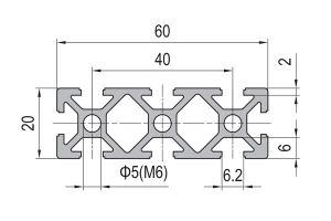 PG20 60 x 20 mm Eight Slot Aluminium Strut Profile Wide Miniature Rail
60 x 20 mm eight-slot aluminium strut profile with 6.2 mm grooves on a…
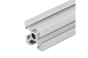 PG20 20 x 20 mm Four Slot Aluminium Strut Profile Miniature Frame
20 x 20 mm four-slot aluminium strut profile with 6.2 mm grooves and 6…
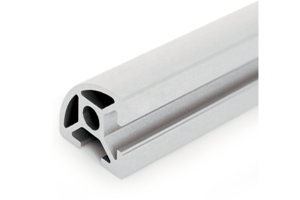 PG20 20 x 20 mm R90 Two Slot Aluminium Strut Profile Rounded Corner
20 x 20 mm quarter-round aluminium strut profile with a swept R90 outer corner…
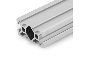 PG20 40 x 20 mm Six Slot Aluminium Strut Profile Rectangular Flat Beam
40 x 20 mm six-slot aluminium strut profile with 6.2 mm grooves on a…
 Aluminium Profile Shelf System 40×40 mm T-Slot Uprights for Workshop Racking
A bolted aluminium profile shelf system in 40 x 40 mm T-slot uprights and…
