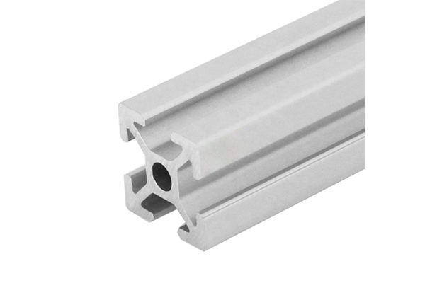
Aluminium 2020 Extrusion 20 x 20 mm for 3D Printer Frames
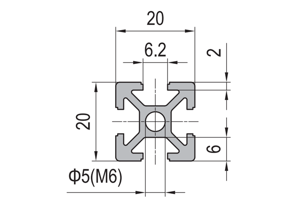
20 x 20 mm four slot aluminium 2020 extrusion for 3D printer and desktop CNC frames. 0.62 kg/m, 6.2 mm groove, 6063-T5, cut to list.
| Material | Aluminium |
|---|---|
| Alloy Grade | 6063-T5 |
| Temper | T5 |
| Section Size | 20 x 20 mm |
| Slot | 4 x 6.2 mm groove, 6 mm mouth, 20 mm pitch, 1 slot per face, M5 and M6 |
| Length | 6 m stock, cut to list to +/-0.5 mm |
| Tolerance | EN 755-9 / GB/T 6892, wall +/-0.15 mm |
| Surface | Mill finish / clear anodised / black anodised |
| MOQ | Made to order; small trial lengths available from stock offcuts |
| Lead Time | Typically 2 to 3 weeks for mill finish, about a week longer for anodising |
| Loading Port | Shenzhen, Guangzhou, Ningbo |
| Supply Ability | Extrusion capacity for standard and custom dies, with in-house saw cutting, drilling and tapping |
| Payment Terms | T/T 30 per cent deposit, balance against copy of bill of lading |
| Trade Terms | FOB, CIF, CFR, EXW |
| Certifications | Mill certificate to EN 10204 3.1 on request, RoHS and REACH declarations |
01Is 20 x 20 stiff enough to build a 3D printer from?
For a static frame, usually yes. For a moving gantry, usually no. That single distinction explains most of the disagreement you will find online, because two people arguing about 2020 are often describing two different jobs. A 400 mm cube frame made of 20 x 20 mm four slot extrusion at roughly 0.62 kg/m is rigid enough to hold a bed and carry a gantry, provided the joints are braced. The same section used as a 400 mm unsupported gantry beam will deflect visibly under its own carriage and will ring for a second after every direction change.
So the useful question is not “is 2020 strong enough” but which part of the machine is the compliant one. On a typical desktop printer the answer is almost never the frame. It is the belt, the toolhead mount, or an unsupported span. Spending money on a heavier frame before identifying the compliant part is the most common way to build a printer that is heavy and still rings.
02Where does the deflection in a printer frame actually come from?
Four sources, in descending order of how often they are the real limit. The frame section is fourth on this list, not first.
| Source | How it shows up | How to tell it is the culprit | Fix |
|---|---|---|---|
| Belt stretch and tension | Ringing that changes with acceleration setting | Ringing amplitude falls sharply when you halve acceleration | Tension the belt, shorten the free span, or fit a wider belt |
| Toolhead and carriage mount | Surface finish worse on one axis than the other | Swap the carriage between axes and the defect follows the carriage | Stiffen the mount, reduce overhang from the rail |
| Unsupported span | Visible sag or bow in the middle of a rail | Deflection scales with the cube of the span — halve the span and it drops eightfold | Add a mid support or step up the section |
| Frame joint slip | Machine loses square after a knock or a transport | Joint witness marks move; fasteners are found below torque | Add corner braces, use a thread locking compound, re-torque to spec |
Note the third row. Deflection falls with the cube of span and only linearly with stiffness. Going from a 400 mm span to a 200 mm span is an eightfold improvement for the cost of one bracket. Going from 20 x 20 to 20 x 40 is also an eightfold improvement in bending, but it costs twice the material and adds mass to whatever has to move. If the span can be shortened, shorten it first.
03How much stiffer is 20 x 40 or 40 x 40, really?
For a beam in bending, stiffness goes with the cube of the depth in the direction of bending and linearly with the width. Taking a solid rectangular section as a reference, the scaling is easy to see. Real extruded sections are hollow, so the absolute numbers are lower — but the ratios between sizes hold closely, and the ratios are what the decision actually depends on.
| Section | Relative bending stiffness (solid reference) | Relative mass per metre | Stiffness per unit mass |
|---|---|---|---|
| 20 x 20 mm | 1.0 | 1.0 | 1.0 |
| 20 x 40 mm, bent about the long axis | 8.0 | 2.0 | 4.0 |
| 20 x 40 mm, bent about the short axis | 2.0 | 2.0 | 1.0 |
| 40 x 40 mm | 16.0 | 4.0 | 4.0 |
| 40 x 80 mm, bent about the long axis | 128.0 | 8.0 | 16.0 |
Two things fall out of this table. First, a rectangular section is only stiff in the direction you orient it — a 20 x 40 laid on its side is barely better than a 20 x 20. Second, stiffness per kilogram grows with the square of depth, so a deep thin section beats a square one of the same mass, every time.
That is why gantry beams on production machines are tall and narrow rather than square. If you are choosing between a 40 x 40 and a 20 x 80 for a gantry, the 20 x 80 is roughly twice as stiff per kilogram in the vertical direction and about the same weight — but it is only stiff in that one direction, so the cross members have to carry the rest.
04What does ringing have to do with section choice?
Ringing is the machine oscillating after a sudden change in direction. Its frequency is set by stiffness divided by moving mass, and its visibility on the part depends on how many oscillations happen before the motion settles. A stiffer frame raises the frequency, which shortens the period, which means the oscillation damps out within a shorter distance of travel. That is the whole mechanism: higher frequency equals shorter ringing marks, not weaker ones.
It also means that adding mass to a moving part makes ringing worse even if it makes the part stiffer, because frequency depends on the ratio. A 20 x 40 gantry beam is eight times stiffer than a 20 x 20 but twice the mass, so the frequency rises by about a factor of two — a real gain, but nothing like the eightfold gain in static deflection. On a moving axis, weight is not free.
Should the frame and the gantry use the same section?
Not necessarily, and often they should not. The frame is static, so mass there costs nothing in dynamics and buys quietness. The gantry moves, so mass there is paid for on every move. A common and sensible split is 20 x 20 or 20 x 40 for the frame and a deeper section, or a different material, for the gantry.
Does filling the profile with sand or epoxy help?
It raises mass without raising stiffness much, so it lowers the resonant frequency — the opposite of what a printer needs. It does add damping, which can reduce the amplitude of the ring. It is a trade, not a free improvement, and on a moving axis it is usually the wrong trade.
05Can a linear rail be bolted straight into the 6.2 mm slot?
Mechanically yes, but not with the rail screw. The 20 series slot is served by M5 and M6 slot nuts, and a typical MGN12 rail is fixed with M3 screws. So the rail does not bolt into the slot directly — you need either a 20 series slot nut with an M3 thread, or a machined adapter plate that picks up the slot with M5 and presents an M3 pattern for the rail.
The adapter plate is the better answer on a machine that has to hold tolerance, for one reason: the slot is not a datum. An extruded slot has a positional tolerance relative to the outside faces, and the outside faces are what the rest of the frame is built from. Bolting a rail into the slot means the rail follows the slot, not the frame. Machining a flat on the profile and mounting the rail to that flat puts the rail on a surface you control.
- Slot nuts are the fast route and are fine for a hobby machine or a jig.
- For anything with a stated straightness, machine a reference face on the profile and mount the rail to it.
- Keep the rail over the web of the profile, not over the slot opening, where the wall is thinnest.
- Use a slot cover strip after assembly — an open slot next to a rail collects chips and they end up under the carriage.
06How tight do the joints have to be?
Tighter than most people expect, and the reason is slip rather than strength. A bolted aluminium joint with a plain washer carries load by friction between the two faces. If the preload is low, the joint does not fail — it slides a few hundredths of a millimetre under a reversing load, and the machine slowly loses square. On a printer that shows up as a frame that was trammed on Monday and is out by Friday.
Three things fix it, in order of cost: a corner brace on every joint that sees a reversing load, a thread locking compound so preload does not decay, and re-torquing after the first thermal cycle — the first time the machine runs warm the joint beds in and the preload drops.
Desktop machine frame checklist
- Longest unsupported span identified and written down before choosing a section
- Gantry beam oriented so its depth is in the bending direction
- Moving mass listed separately from static mass
- Corner braces on every joint that sees reversing load
- Slot nuts sized to the rail screw, or an adapter plate if they do not match
- Slot cover strips specified for slots that stay open
- Cut list with diagonal check, not just per-piece length
- Re-torque step scheduled after the first warm run
07Questions from people building a desktop machine
Related sections and categories
Browse 20 Series Aluminium Profiles, Strut Profiles, the 20 x 20 mm four slot section, or see the 20 x 40 mm six slot beam for the full section data.
What is the difference between this and the 20 x 40 six slot section?
This is a 20 x 20 square with one slot per face. The 20 x 40 is a rectangular section with six slots and about 0.80 kg/m, and it is roughly eight times stiffer in its strong direction. Use the square for frames and uprights, the rectangle for beams and gantries where the load direction is known.
Do you supply cut-to-length kits with the fasteners?
Yes. Send a cut list and we will supply the profiles cut to length, the slot nuts and the corner braces matched to the slot, packed by sub-assembly. A kit is quoted against the cut list rather than per metre because the cutting and the packing are the labour content.
How square is a cut frame likely to be?
Piece length is plus or minus 0.5 mm. On a closed frame that accumulates, so a 400 mm cube can be up to about 2 mm out on the diagonal if every piece lands at the same end of tolerance. Check the diagonal before tightening, and specify a diagonal tolerance if the frame has to be square.
Can the profile be supplied pre-drilled for the rail pattern?
Yes, drilled to drawing on a jig. Send the rail datasheet hole pattern and the position of the rail relative to the reference face; the critical dimension is the offset from the machined face to the rail centreline, not the hole spacing.
Is 6063-T5 suitable for a printer frame?
It is what the 20 series is stocked in, and it machines and anodises cleanly. Its yield strength is lower than 6061-T6, so for a frame carrying a heavy bed or a long span, ask for 6061-T6 on the larger sections rather than on this one.
What to send for a 2020 printer frame quote
- Cut list with lengths, quantities, and which faces need machining
- Longest unsupported span and the load on it, so the section can be checked
- Rail type and hole pattern if the profile is to be drilled
- Whether the frame is a kit with fasteners or profiles only
- Finish: mill, clear anodised or black anodised
- Quantity in metres or number of complete frames
- Any diagonal or squareness requirement on the assembled frame
A sketch of the frame with the moving axis marked is more useful than a parts list, because it shows which sections carry load and which only close the box.
Send a cut list and the longest span
Tell us the frame size, the longest unsupported span and what moves. We will check the section against the span, and quote the profiles cut to list with the slot nuts matched to your fasteners.
Request a quotationRelated Products
 Aluminium 2020 Profile 20 x 20 mm for Laboratory Instrument Stands
20 x 20 mm aluminium 2020 profile for laboratory instrument stands. 0.62 kg/m, 6.2…
20 x 20 Aluminium Extrusion 6.2 mm Slot Stock Lengths and MOQ
20 x 20 mm aluminium extrusion with a 6.2 mm slot, supplied in 6…
 Aluminium 60 x 60 mm Four Slot Extrusion for Robot Cell Gantries
60 x 60 mm four slot aluminium extrusion for robot cell gantry columns and…
 Aluminium 4040 Extrusion 40 x 40 mm Single Slot for Machine Fixtures
40 x 40 mm single slot aluminium 4040 extrusion for machine fixture bases. Three…
 Aluminium 40 Series Extrusion 40 x 40 mm for PV Module Lines
40 x 40 mm aluminium 40 series extrusion for photovoltaic module lines. Four slots,…
 Anodised Aluminium Profile 40 x 40 mm AA15 Clear Finish for Visible Frames
40 x 40 mm anodised aluminium profile in 6063-T5 with an AA15 clear anodised…
 CNC Machined Aluminium Profile 40 x 40 mm Drilled and Tapped Cut List
40 x 40 mm aluminium profile supplied CNC machined to a cut list: saw…
 Aluminium Profile Sliding Door 40 Series 8 mm Slot for Machine Enclosures
Sliding door leaves framed in 40 series aluminium profile for machine enclosures. Top hung…
