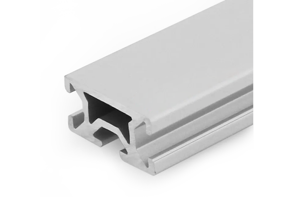
The question arrives in almost the same words every time: “I have an existing frame — Misumi hardware, or an imperial 15-series line, or a Bosch-built cell — and my supplier says their 40 mm profile is ‘standard metric’. Will it fit?”
The answer is not a brand verdict. It is a measurement. Cross-brand compatibility in aluminium framing is decided by four dimensions, and every one of them is checkable with a caliper, a feeler gauge and about ten minutes at the goods-in bench. The reason this is worth doing rather than trusting a catalogue claim is that the failure mode is quiet: a T-nut that slides into a slot but does not lock, a gusset whose bolt holes are 0.9 mm off, a frame that assembles in the jig and works loose on the line six weeks later.
This article is written for the engineer who has to make the call — typically someone integrating a new automation cell into a plant that already has framing history, or a maintenance engineer who has to add a station to an existing bench. It sets out what the main framing standards actually are, the four measurements that decide compatibility, the arithmetic of pitch mismatch over a long span, the legitimate ways to bridge two systems, and the wording that turns “compatible” from a marketing adjective into a specification.
Before the brand arguments
One thing worth saying plainly at the start, because the marketing around this subject is unusually aggressive. Every framing manufacturer claims its slot is the correct one and every other slot is a compromise. In reality the systems are not better or worse, they are different, and the differences are traceable to which national engineering tradition each one grew out of. A German automation standard and a Japanese factory-automation standard and a North American machine-building standard genuinely needed different things. Your job is to find out which family your plant is already speaking, not which one a supplier prefers to sell.
Quick answer
Nine things that decide whether the parts will fit
Items 1 to 3 are the technical core. Item 8 is the one that prevents the argument, and item 9 is the one that prevents a surprise on the invoice.
Compatibility is four numbers, not a brand Slot opening width, slot lip thickness and internal pocket form, centre bore diameter and thread, and slot pitch. Measure those four and the question is answered.
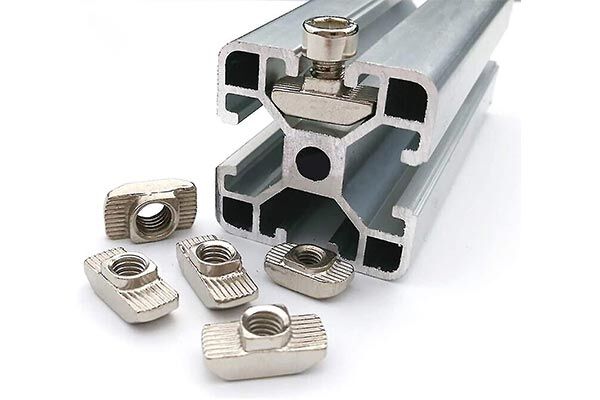
A nut that slides is not a nut that locks Imperial 15-series slots commonly carry an angled inner flange — the “drop-lock” form — while metric slots are usually flat-walled. A metric nut in an imperial slot can enter and still not develop clamping force.
Pitch is where long frames go wrong A 1.5 inch module is 38.1 mm. Against a 40 mm metric module the error is 1.9 mm per span, and it accumulates: ten spans is 19 mm.
The 0.2 mm rule is real but incomplete Slot width mismatch of 0.2 mm will stop a standard T-nut locking reliably. It is not the only failure mode — lip geometry and pocket depth matter too.
Measure the opening, not the slot The dimension that governs fastener fit is the opening between the slot lips, not the wider internal pocket. Both must be checked.
Centre bores are not interchangeable either A tapped centre bore for M8 and one for 5/16-18 differ in drill diameter and in thread form. Re-tapping one into the other rarely leaves enough material.
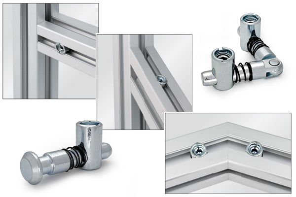
Two systems can coexist, with a deliberate bridge A transition plate or an adapter nut is a legitimate engineering solution. Forcing a mismatched nut with a longer bolt is not.
Put a number in the contract “MayTec compatible” is unenforceable. “Slot opening 8.2 +0.1/−0 mm, measured 5 mm from the end” is a specification you can reject against.
Classification changes the landed cost Bare extruded profile and an assembled frame are different tariff headings. The heading affects duty, and it affects whether a trade measure applies at all.
Landscape
The framing systems you are actually choosing between
There is no single world standard for T-slot framing. There are four or five families, each internally consistent and each with a different idea of what the basic module should be. Understanding which family a plant speaks is the first step, because the family determines what an “existing” drawing actually means.
| Family | Module basis | Typical series | Slot opening | Notes |
|---|---|---|---|---|
| Metric industrial framing (European and Asian mainstream) | Base-10 millimetre grid | 20, 30, 40, 45, 60, 80, 90 | 6, 8 or 10 mm | Clean modular arithmetic. Cross-section dimension equals the grid module, so a 4040 is 40 × 40 mm on a 40 mm centre-to-centre pitch. |
| Imperial structural framing (North American) | Fractional inch | 10-series (1″), 15-series (1.5″), 20-series (2″) | 1/4″, 5/16″, 3/8″ | The 15-series slot often has an angled inner flange that develops a spring tension under load. Metric pitches and fractional pitches do not divide into each other. |
| Japanese factory-automation standards | Metric, but proprietary series naming | 5-series (20 mm), 6-series (30 mm), 8-series (40 mm) | Usually 6 or 8 mm | Metrically dimensioned but with proprietary bore and pocket geometry. The series numbers refer to the brand’s own catalogue, not to a shared standard. |
| German automation framing standards | Metric, base-10 grid | 40 mm, 45 mm, 60 mm, 90 mm | 8 mm and 10 mm variants | Two different German traditions exist with different slot openings on the same nominal cross-section. This is the single most common source of “it should have fitted”. |
| Slot-and-bolt architectural systems | Metric and imperial both | Varies | Varies | Structurally similar but dimensioned around architectural module sizes rather than machine framing. Rarely interchangeable with the above. |
The point of the table is not to rank these systems. It is to show that “40 mm profile” and “8 mm slot” do not identify a part. The nominal cross-section and the slot opening are only two of the four dimensions, and the other two — pocket geometry and centre bore — are where most cross-brand attempts actually fail.
Method
The four measurements that decide it
Everything that follows depends on four numbers. Take them on the profile you already have and on a sample of the profile you are being offered, and compare like with like — the same distance from the cut end, the same slot face, the same temperature.
Slot opening width
The gap between the two slot lips, measured across the narrowest point of the opening. Use a caliper with the jaws parallel to the slot axis and take three readings along the length. This is the dimension a T-nut’s shank has to pass through, and it is the dimension the “0.2 mm” rule refers to. A difference of 0.2 mm between the nut’s shank width and the slot opening is enough to prevent the nut rotating into its locking position.
Slot lip thickness and pocket form
The lips are the two cantilevered edges that carry the clamping load. Measure lip thickness with the caliper depth rod, then look at the pocket behind the lips with a light: a flat-walled rectangular pocket and an angled or “drop-lock” pocket take different nut profiles. A nut designed for a flat pocket will sit on the angled face of a drop-lock slot and clamp over a line contact instead of a face, which is how a joint passes a torque check and then loosens under vibration.
Centre bore diameter and thread
The bore down the core of the profile, and its thread if it is tapped. Measure the bore with the caliper internal jaws or with a pin gauge. If it is tapped, identify the thread with a thread gauge — metric and unified threads are not interchangeable, and the difference between M8 and 5/16-18 is visible but easy to miss. The bore also sets the maximum bolt size, which in turn sets the load a corner joint can carry.
Slot pitch
Centre-to-centre distance between adjacent slots on the same face, and between opposite faces. On a single-slot-per-face profile the pitch equals the cross-section dimension, but on multi-slot profiles it does not, and it is the multi-slot case where cross-brand brackets fail. Measure the pitch across a long run, not just one span, because that is where the arithmetic error shows up.
What to record, and how to take each reading
The measurement everyone forgets
Do not measure a profile with a coating on it and compare it with an uncoated one. Anodising and powder coating add to every external dimension, and on a tight-tolerance slot that added film can be the difference between a nut that slides and a nut that has to be tapped in with a mallet. Always specify and measure on the same finish state, and if you must compare across finishes, note the film thickness on both sides of the comparison.
Tolerance accumulation
Why long frames fail: the pitch arithmetic
Short assemblies made from mismatched systems often work. Long ones usually do not. The reason is that pitch error accumulates linearly while the compliance in each individual joint does not, so the assembly absorbs a small mismatch per joint until the total exceeds what the joints can take up — and then the last panel or the last bracket simply will not go in.
Accumulated error Δ = N × (Pa − Pb)
where N = number of modules, Pa and Pb = the two pitches
Example: N = 10, Pmetric = 40.0 mm, Pimperial = 38.1 mm (1.5″)
Δ = 10 × 1.9 mm = 19 mm
Nineteen millimetres is not a tolerance. It is more than half a slot pitch, and no amount of joint clearance will absorb it. This is why a frame that assembles perfectly in a two-module test rig fails completely at production length, and why the failure is always blamed on the supplier who shipped the newest batch of profiles.
The same arithmetic applies with a smaller constant in the metric-to-metric case, and it is the reason two nominally identical metric systems can still fail. A difference of 0.05 mm in pitch is invisible on a single span and becomes 5 mm over a hundred modules — which is the length of a conveyor guard or a machine enclosure run. Any supplier claiming interchangeability should be able to state a pitch and its tolerance, not just a cross-section.
The three failure signatures, and what each one means
| What you see | Most likely cause | What to do |
|---|---|---|
| Nut enters the slot but will not rotate into the locked position | Slot opening narrower than the nut shank, or pocket form mismatch (flat-walled nut in a drop-lock slot) | Measure opening and pocket form. If the opening is out of specification, reject. If the pocket form differs, you need a nut matched to the slot, not more force. |
| Joint torques correctly and loosens within weeks | Line contact between nut and lip instead of face contact; insufficient lip engagement; or no thread-locking provision on a vibrating machine | Check nut-to-lip contact pattern. Use a serrated or spring nut matched to the slot geometry, and add a thread-locking element. |
| Frame assembles in the jig and will not close at final length | Pitch accumulation. The error is distributed along the run and only becomes visible when the last member is fitted. | Measure pitch over five or more modules. Either standardise on one system for the whole run or introduce a deliberate adjustable transition. |
| Bracket bolt holes will not align | Gusset or plate dimensioned to the other system’s hole spacing, not to a pitch error | This is a plate geometry problem, not a profile problem. The plate is the cheapest thing to change. |
| Bolt bottoms out before the joint is tight | Centre bore tapped to a shallower usable depth, or the bolt is bottoming on a blind bore because the profile core is smaller | Measure usable thread depth. Never shorten a bolt and call it a fix without recalculating the engagement. |
Every one of these signatures has been attributed to “bad profiles” at some point. Only the first two are profile problems. The third is a system-mixing problem, and the fourth and fifth are drawing problems — which is good news, because drawings and plates are cheap to change.
Practical test
The ten-minute goods-in check
This is the procedure worth putting in the incoming inspection plan. It needs no special equipment beyond what a machine shop already owns, and it catches the great majority of cross-brand fit failures before the profiles reach the assembly bench.
The nut test is the decisive one, and it is worth explaining why. A nut from system A will either run freely in a slot and lock, or it will not. There is no interpretation required and no supplier can argue with the result. Where the test is ambiguous — the nut runs but feels stiff — that is itself the finding: a stiff nut is a nut that will not reach its rated clamping force, and it will be the joint that loosens first.
Integration
Bridging two systems without pretending they are one
Sometimes standardising on a single system is not available to you. A plant with an installed base of one system may be adding equipment designed around another, or a project may inherit a competitor’s frame that has to be extended rather than replaced. In that situation the engineering answer is to build a deliberate transition rather than to hope the parts will meet in the middle.
Legitimate transitions
- A transition plate machined to carry one system’s hole pattern on one half and the other’s on the other half, bolted to each system with its own fasteners.
- A matched nut and bolt set for each side of the joint, with the plate taking up the geometry difference rather than the fastener.
- A floating or slotted connection where the two systems meet, sized to absorb the pitch error over the length of the transition rather than at a single point.
- A purpose-made extrusion with the target system’s slot on one face and the legacy system’s geometry on the other, if the volume justifies a die.
- A documented interface drawing that names both systems, states the measured dimensions, and is attached to the assembly instructions.
Practices that fail
- Drilling out a nut or a bracket to make a larger fastener pass. The clamping face is what carries the load; enlarging the hole removes it.
- Using a longer bolt to force a nut into a slot it was not designed for. This loads the lips in bending rather than in compression and can crack them.
- Re-tapping a centre bore from one thread form to another without checking the remaining wall. Aluminium gives up wall thickness quickly, and a stripped centre bore condemns the whole profile.
- Mixing systems within a single load path and calling it a prototype. The prototype works because it is short; the production frame does not.
- Relying on joint clearance to absorb pitch error. Clearance is a manufacturing tolerance, not a design allowance.
The pattern in the two columns is the same: legitimate transitions put the geometry difference into a part designed to carry it. Practices that fail put the difference into a fastener, which is the smallest and least forgiving element in the assembly.
The strategic option
There is one more option that is often overlooked because it does not feel like engineering: standardise the plant. If a site has accumulated three framing systems over fifteen years, the cost of a fourth is not the profiles, it is the inventory, the spares, the tooling and the training. A deliberate decision to freeze on one system, retire the others as their equipment is replaced, and hold a documented interface standard for the transition period is usually cheaper than remaining multilingual indefinitely.
Contract
How to write compatibility into a purchase order
The reason cross-brand compatibility arguments are so tedious is that the requirement is usually written as a claim rather than a specification. “MayTec compatible” or “fits standard T-slot hardware” cannot be inspected, so it cannot be enforced. The fix is to convert the claim into dimensions and a test, and to put both on the order.
| Instead of | Write |
|---|---|
| “Compatible with standard T-slot hardware” | “Slot opening 8.2 mm +0.1/−0, measured on the slot face at 5 mm and at mid-length.” |
| “Standard metric profile” | “Cross-section 40 ±0.15 mm × 40 ±0.15 mm; slot pitch 40 ±0.10 mm measured over five modules.” |
| “Fits our existing hardware” | “A sample T-nut supplied by the buyer shall run and lock in the slot without tools, tested on three pieces per batch.” |
| “Centre bore tapped as standard” | “Centre bore tapped M8×1.25 to a minimum usable depth of 15 mm; thread gauged per batch.” |
| “Tight tolerances” | Name the standard and the grade. State the alloy and temper separately: “6063-T5 per the referenced extrusion standard, wall thickness ±0.15 mm.” |
| “We will inspect on arrival” | “Buyer may reject any batch failing the nut test or the dimensional check. Supplier to supply a dimensional record per heat number.” |
Two further clauses are worth adding for any project that crosses systems. First, a change notification requirement: the supplier must notify you before changing a die, a bore or a slot geometry, because that is how a compatible part becomes an incompatible one without anyone deciding to make it so. Second, a sample retention clause: keep a reference sample from the approved first article, sealed and dated, so that a future dispute has a physical baseline rather than a drawing interpretation.
Landed cost
The classification question, which nobody mentions
Compatibility determines whether the parts fit. Classification determines what you pay to get them into the country, and the two are unrelated — which is exactly why classification is so often overlooked. A supplier quoting “HS code 7616999000” for a bare extruded profile is describing the goods as an article of aluminium rather than as a profile, and that choice can change the duty, the documentation, and whether a trade measure applies.
Why the heading changes the invoice
| What you are actually importing | Heading family | Why it matters |
|---|---|---|
| Bare extruded profile, cut to length, not further worked | The aluminium bars, rods and profiles heading, with a separate sub-heading for hollow profiles and for other profiles | This is the classification for the material itself. It is the heading most extruders should be using for profile sold as profile. |
| Profile that has been machined, drilled, tapped or assembled into a frame | Headings for structures and parts of structures, or for other articles of aluminium, depending on the degree of working | Further working moves the goods out of the material heading. A frame is not a profile for customs purposes. |
| Fasteners, brackets, connectors, T-nuts | Other articles of aluminium | Small hardware is classified as hardware. It does not follow the profile classification. |
| Finished machine guard or enclosure presented as a machine part | Depends on whether it is presented as a structure or as a machine part | This is the case where classification genuinely changes the answer, and where a broker should be consulted before the order is placed. |
The practical point is not that one heading is right and another is wrong. It is that the heading is a decision with commercial consequences, and that a supplier who quotes a single code without asking what the goods are and how far they have been worked has not done the analysis. Ask for the code they intend to declare, the reasoning, and a confirmation that the description on the commercial invoice matches the goods.
Trade measures are scope-based, not code-based
Aluminium extrusions from China have been the subject of anti-dumping and countervailing duty action in more than one major market, including measures introduced in the United States in 2024. Those measures are company-specific and scope-specific: whether they apply depends on the exporting entity, the product form, and the origin of the metal. Do not treat a duty rate from a quote as current, and do not assume that a different tariff heading removes the goods from a measure’s scope. Verify the current scope and the applicable rate for your specific supplier and product with a customs broker before you price a project.
There is a second-order commercial effect worth planning for. If a trade measure applies to one product form and not another, buyers sometimes respond by importing the goods in the form that attracts less duty and doing the further working themselves. That is a legitimate manufacturing decision when the working is genuinely done in the importing country and the classification reflects what the goods actually are. It is a compliance problem when the goods are described as something they are not. The distinction is the physical state of the goods at the border, not the intent of the buyer.
FAQ
Frequently asked questions
Check the interface on the real section
Metric and imperial profiles, and the hardware that joins them
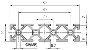
Compatibility comes down to slot geometry, which is published per section. Compare the entries below against the imperial series you already hold before committing to a conversion kit.
Extending a frame built to another system?
Send us the slot opening, lip thickness, centre bore and pitch you have measured, or a sample of the profile you need to match. We will tell you whether our standard profiles fit, and where they do not, we will quote a transition plate or a purpose-made section rather than let you find out on the assembly bench.
Related reading
Twelve more engineering notes from this blog, picked for this article — plus every category below.
 ApplicationsAluminium Profile Display Boards: The Panel Is the Hard Part
 Materials and EngineeringIndustrial Aluminium Extrusion: Five Advantages and the Conditions Attached to Each
 Applications20 Series T-Slot Profiles: Where the Limits Actually Are
 Materials and EngineeringAnodised vs Powder Coated Aluminium Profiles: A Specification Guide for European Buyers
 ApplicationsWhy T-Slot Aluminium Profiles Are Used in Automation and When They Are Not
 Materials and Engineering6063-T5 Aluminium Profile: What the Designation Actually Guarantees
 Engineering DesignCross-Brand T-Slot Compatibility: Interchangeability Is a Hardware Question
 Engineering DesignWhat Your Extrusion Drawing Must Show (and What Costs You Money)
 Sourcing and ProcurementPayment Terms for Aluminium Profile Orders (T/T, L/C and the Risk)
 Machine SafetyAluminium Profile Machine Guards: Size the Frame from the Energy, Not from the Mesh
 Quality and InspectionGood vs Bad Aluminium Profiles: What Your Receiving Dock Can and Cannot Check
 Sourcing and ProcurementAluminium Profile MOQ: 150 m Existing Die, 500 m New
