Quick answer
What actually decides a corner bracket choice
Five things, in this order. Everything else is packaging.
Slot geometry, not profile size. A 40-series profile has an 8 mm slot mouth and a 30 mm bolt pitch. A 45-series has a 10 mm mouth. A bracket drilled for 10 mm will not hold position on an 8 mm slot even if the outer dimensions look close.
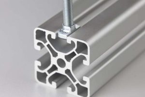
The T-nut is the weak link — not the bracket. A die-cast gusset in ADC12 will outlast the aluminium threads it is bolted into. Design for T-nut pull-out and you have designed the joint.
External brackets are pin-jointed in practice. They carry force well and moment badly. If the frame must resist sway, the bracket alone is not the answer.
Bolt torque is a specification, not a preference. M8 into a 40-series T-nut: 10–15 N·m, with a ceiling of about 15 N·m set by the slot lip. Below that the joint creeps; above it you deform the lip the nut bears on.
Count brackets by geometry, not by feel. Every three-way corner takes two brackets. Every two-way corner takes one. That single rule gets a 4040 workstation right the first time.
The part everyone skips
What a corner bracket is really doing inside a joint
An external corner bracket is not a hinge and it is not a weld. It is a moment couple with a short lever arm, and almost every field failure traced back to a bracket starts with someone treating it as a rigid connection.
Put a horizontal 40x40 beam into a vertical post with one gusset and load the beam 500 mm out. The beam wants to rotate about the corner. The bracket resists that rotation with two forces pulling in opposite directions along the bolt line: the bolt nearest the corner goes into compression against the profile, the bolt furthest away pulls out.
That gives you the only equation you need at concept stage:
M = F × LThe joint moment equals the load times its distance from the corner. A 400 N load at 500 mm is a 200 N·m moment at the joint — before any safety factor.Now convert that moment into a force on the fastener. For a 40-series gusset with two bolts on a 40 mm spacing, the couple arm is roughly 40 mm, so:
Fbolt = M / d = 200 N·m / 0.040 m = 5,000 NFive kilonewtons of pull-out on a single M8 T-nut, from a load a person can lift. This is why “it’s only a small bracket” is how frames get loose.This is the number that matters. Not the bracket’s outer size, not whether it is die-cast or machined, and not the marketing photo. A standard 40-series M8 T-nut in an 8 mm slot is rated at roughly 1.5–2.2 kN of pull-out per nut in the standard section; the 20 mm long-body version engages more of the slot lip and raises that figure. A 200 N·m joint moment needs 5,000 N of bolt force. That is more than twice what one nut can hold, so this joint — built with a single bracket pair — is already over capacity.
Run the calculation backwards and you get the real ceiling of an external bracket joint:
Mmax = Fnut × d = 2,200 N × 0.040 m ≈ 88 N·mAbout 88 N·m for a bracket pair on a 40 mm bolt pitch, using the optimistic end of the nut rating. Apply a safety factor of 2 and the working figure is roughly 44 N·m per bracket pair.The design consequence
If your calculation lands above about 60% of the T-nut pull-out figure — roughly 0.9–1.3 kN for a 40-series M8 nut — you do not need a “stronger bracket”. You need a different joint: a second bracket in the other plane, an internal anchor connector, a longer bolt spacing so the couple arm grows, or several brackets along the joint.
The hardware
The five bracket families and what each one is for
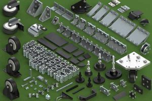
Suppliers list dozens of part numbers. They collapse into five functional families, and each one solves a different problem. Choosing the family is the decision; choosing the part number is administration.
Die-cast gusset bracket
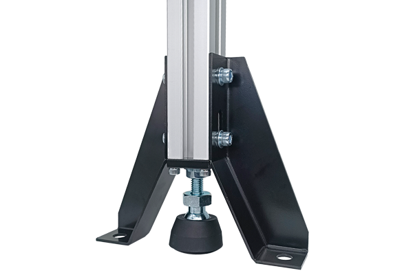
A right-angle plate, usually 4–5 mm wall, cast in ADC12 or A380 and often with a locating rib. Two bolts into each profile. This is the default for 90° joints on 30, 40 and 45 series frames. Cheap, repeatable, and the first part to reach for on a machine guard or a workstation. Its limit is rotational stiffness, not strength.
L-base and base-angle bracket
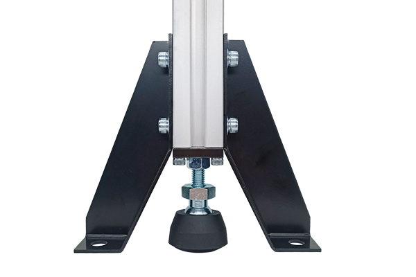
A heavier, wider-footed bracket used where a leg meets a floor rail or where the joint also carries a bending load from the base. Wider bolt spacing raises the couple arm, which is the cheapest way to raise joint moment capacity without changing anything else.
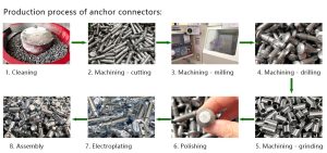
Anchor connector / end fastener
A bolt and expanding sleeve that pulls the end face of one profile against the side of another. This is the strongest option in direct axial pull-out and the cleanest externally, because nothing protrudes. It is also the worst at resisting rotation: the joint can pivot about the bolt axis unless a bracket or plate backs it up.
Joining plate
A flat or stepped plate bolted across a butt joint or a T-joint. Use it to extend a profile beyond standard stock lengths, to stiffen a splice, or to tie a cross member into a long rail where a gusset would foul a panel.
Pivot and swivel connectors
Adjustable-angle joints for sloped guards, angled bracing and position-adjustable fixtures. Treat them as pinned: they locate, they do not brace.
Combination joints
The strongest practical joint on a T-slot frame is usually an anchor connector plus an external gusset, or a gusset plus a joining plate. One resists pull-out, the other resists rotation, and together they behave far closer to rigid than either alone.
The failure that matters
Why the T-nut, not the bracket, decides your joint
Ask a supplier what a bracket is rated for and you will often get a compressive load figure that looks reassuring and describes a test nobody performs in service. In a real 90° joint, the bolt is not being crushed. It is being pulled out of an aluminium nut that sits in an 8 mm slot.
Rank the components by how much abuse they take before something yields:
| Component | Failure mode | Typical 40-series M8 value | Who fails first |
|---|---|---|---|
| Die-cast gusset bracket | Bending of the plate, boss cracking | Well above the nut’s limit | Almost never |
| M8 bolt, grade 8.8 | Shear or tensile rupture | ~14 kN shear, ~23 kN tension | Rarely |
| M8 T-nut, 8 mm slot | Thread strip, slot flange deformation | ~1.5–2.2 kN axial | Usually |
| Profile slot wall | Local flange yield under the nut | Same order as the nut | Often, on soft temper |
| Bolt torque as applied | Preload loss, joint creep | Spec 10–15 N·m, ceiling ~15 N·m | On site, all the time |
Read that table the other way round and the design rule falls out: you cannot make a joint stronger by buying a beefier bracket. You make it stronger by spreading the load over more nuts, by increasing the bolt spacing so the couple arm grows, or by changing the joint type.
Watch out
Two suppliers can quote the same “4040 corner bracket” and give you different capacities, because one measured the bracket and the other measured the assembly. Always ask what the number describes: bracket alone, or bracket plus specified nut plus specified torque.
Assembly data
Bolt, nut and torque selection for 30, 40 and 45 series
This is the table that prevents the most common field problem: a joint that is visually correct, finger-tight, and creeping under vibration three weeks after commissioning.
| Profile series | Slot mouth | Bolt / nut | Working torque | Torque ceiling | Notes |
|---|---|---|---|---|---|
| 20 series | 6 mm | M5 T-nut, 10 mm cavity | ~3 N·m | ~3 N·m | Light frames, enclosures, displays. Hand tools only |
| 30 series | 8 mm | M6 T-nut, 12 mm body | 5–6 N·m | ~6 N·m | Benches, small guards, jigs. Pull-out ~600–900 N per nut |
| 40 series | 8 mm | M8 T-nut, 15 mm body | 10–15 N·m | ~15 N·m | The workhorse. Pull-out ~1.5–2.2 kN per nut; the 20 mm long body lifts it |
| 45 series | 10 mm | M8 T-nut, 15 mm body | 10–15 N·m | ~15 N·m | 10 mm mouth, 33 mm pitch. Not interchangeable with 40 series |
| 50 and 60 series | 10 mm | M10 T-nut, 20 mm body | 20–30 N·m | ~30 N·m | Gantries, heavy bases. Pull-out ~3.5–5.0 kN per nut |
Three practical notes that no catalogue prints:
- Torque is a range with a hard ceiling. The lower bound is what stops the joint loosening under vibration; the ceiling is where the aluminium slot lip or the nut thread starts to deform, and it is set by the profile, not the bolt. A grade 8.8 steel M8 screw can take far more than 15 N·m — the aluminium under it cannot.
- The torque ceiling rises with the nut body length. A 20 mm long-body nut engages more of the slot lip than a 15 mm standard body, which is why the long-body option exists for loaded corners. It costs a little more and buys real capacity.
- Anodising changes the fit. A hard anodised profile adds 20–40 µm to each surface, which tightens the slot mouth. If you are running anodised frames and standard nuts, order the nuts to the anodised slot, not the mill-finish slot.
Quantity
How many corner brackets does the frame actually need
Ignore “one per corner”. Count the joints by how many members meet there, because that is what determines how many planes need bracing.
brackets = (2 × three‑way corners) + (1 × two‑way corners)Every three-way corner — two rails plus a leg — needs a bracket in each of the two vertical planes. A two-way corner, such as a mid-rail meeting a leg, needs one.Worked example: a 4040 workstation, 1200 × 700 × 850 mm
Four legs, a top frame and a lower rail frame. Take the top frame first: each of its four corners is three-way, because two rails and one leg meet there. That is 4 × 2 = 8 brackets. The lower rail frame is the same: 8 brackets. Total 16.
Add the practical extras that separate a frame that lasts from one that wobbles:
- Diagonal bracing. If the frame is taller than it is wide and has no panels, add a diagonal brace or a joining plate across one plane per side. This does more for rigidity than any bracket upgrade.
- Foot or castor plates. Each leg base takes a foot or a levelling castor, which is a separate connection and needs its own fasteners.
- Spares. Order 10% extra nuts and brackets. They are the parts that get dropped, cross-threaded and lost during commissioning, and re-ordering 20 pieces costs more in freight than the parts.

Selection
A six-step selection sequence that produces a part number
Write down the series and slot mouth for every member in the joint. If two different series meet, you need an adapter plate, not a bracket.
Two-way or three-way. External access or concealed. Fixed angle or adjustable. This picks the family before you look at a catalogue.
Load times distance to the joint. Include the weight of anything mounted on the member, not just the payload.
M / d, with d as the bolt pitch on the bracket. If the result is over about 60% of the nut’s pull-out figure, change the joint rather than the bracket.
Panels, guards and doors need a frame that resists sway. If it does, add bracing or a second connection type. External gussets alone behave close to pinned.
Series, slot mouth, bolt size and grade, torque, material, finish and hole tolerance. That is what turns a bracket into a part you can reorder.
Incoming inspection
What to check when the brackets arrive
Corner brackets are cheap enough that most buyers skip inspection entirely, then discover the problem at assembly when 200 frames will not go together squarely. Five checks catch nearly everything.
Procurement
What to put on the RFQ so the second order matches the first
The reason bracket sourcing goes wrong is rarely price. It is that the specification was verbal, so the second shipment is “the same part” from a different die with a different hole position.
| Specify | Example value | Why it matters |
|---|---|---|
| Profile series and slot mouth | 40 series, 8 mm slot, 30 mm pitch | Prevents a 45-series part arriving with the same outline |
| Material and process | Die-cast ADC12, or 6063-T5 machined | Cast and machined parts are not interchangeable in tolerance |
| Hole pattern and tolerance | 2 × Ø8.4 mm, pitch 40 mm, ±0.2 mm | Controls assembly fit and repeatability across lots |
| Finish | Mill, or anodised 10–20 µm | Affects slot fit on anodised profiles |
| Fastener pairing | M8×20, grade 8.8, with 40-series T-nut | Lets the supplier validate the assembly, not just the part |
| Packing | Counted bags per size, carton marked with series | Stops mixing at the assembly bench |
Two more clauses worth adding on a first order: a sample approval step (first-article inspection against a drawing before the balance of the order ships) and a lot traceability note (alloy certificate and inspection record retained for the batch). Neither adds cost. Both remove the failure mode that costs the most — a frame built from two batches of brackets that do not match.
If you are building the joint from scratch, the bracket is one line of a four-line bill: profile, bracket, nut, bolt. The other three lines are described on our 40 series aluminium profiles page, and the fasteners are grouped under fastening elements. For the profile itself, 4040 4-slot strut profile is the usual starting point, and the matching nut is 40 series T-nut.
Frequently asked questions
What is an aluminum profile corner bracket used for?
It joins two aluminium extrusions at 90°, most often in machine frames, workstations, guards and equipment stands. It is an external, mechanical connection, so the frame can be assembled with hand tools and taken apart again without cutting or welding. Its job is to hold position and carry the joint moment; the fasteners carry the load.
How do I know if my joint needs a stronger bracket or a different joint?
Calculate the joint moment as load times distance to the corner, then divide by the bolt pitch on the bracket to get the bolt force. If that force is above roughly 60% of the T-nut pull-out rating — about 1.5–2.2 kN for an M8 nut in the 8 mm slot of a standard 40-series section — a stronger bracket will not help, because the nut is the limit. Increase the bolt spacing, add a second bracket in the other plane, or add an anchor connector.
Can one corner bracket fit different aluminum profiles?
Only within the same series. A 40-series bracket is drilled for an 8 mm slot mouth and a 30 mm pitch. A 45-series profile has a 10 mm mouth. The outer dimensions may look close enough to fool a photo comparison, but the bolt will not seat correctly and the joint will not hold position. Cross-series joints need an adapter plate.
Do corner brackets need T-slot nuts, and what torque should I use?
Yes — on a T-slot system the bracket is bolted through a T-nut or drop-in nut that sits in the slot. Recommended torque is about 3 N·m for M5 into a 20-series nut, about 6 N·m for M6 into 30 series and about 15 N·m for M8 into 40 series, which is also the ceiling. Exceeding the ceiling deforms the nut thread or the slot lip it bears on, which is a permanent loss of capacity.
Are corner brackets strong enough for a machine frame?
For strength, usually yes. For rigidity, often no. External gussets behave close to pin-jointed, so a tall frame braced only with brackets will sway. Add diagonal bracing, a joining plate across a plane, or an anchor connector combined with the bracket. The bracket carries the force; the bracing controls the deflection.
What is the difference between a corner bracket and an anchor connector?
A corner bracket sits outside the joint and resists rotation with a short couple arm. An anchor connector sits inside the profile and pulls the end face against the other member, which makes it much better in direct axial pull-out and invisible from outside. Use the bracket for moment and access, the anchor for axial strength and a clean appearance, and use both when the joint has to do both jobs.
Need brackets, nuts and profiles that are specified together?
We extrude and machine the profile, cast and machine the brackets, and supply the matching nuts and bolts as one assembly — so the hole pattern, the slot fit and the torque spec agree.
Related reading
Twelve more engineering notes from this blog, picked for this article — plus every category below.
 Engineering DesignT-Slot Aluminum Profile Connectors: What Each Type Is Actually Good At
 Engineering DesignAluminium Profile Basics: What the Series Numbers and Slot Codes Mean
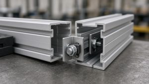 Engineering DesignHow to Join Aluminium Profiles: Joints, Brackets and Torque
 ApplicationsAluminium Profile for LED Strips: A Heat Sink First, a Housing Second
 ApplicationsAluminium Partitions: The Three Performance Numbers Behind the Aesthetic
 Engineering DesignWhat Your Extrusion Drawing Must Show (and What Costs You Money)
 Materials and EngineeringRecycled Aluminium Profiles: A Number You Have to Be Able to Evidence
 Engineering DesignCross-Brand T-Slot Compatibility: Interchangeability Is a Hardware Question
 Sourcing and ProcurementImporting Aluminum Profiles from China: Nine Failures That Quietly Raise Your Landed Cost
 Sourcing and ProcurementAluminium Profile Price Breaks: How Volume Changes the Unit Price
 Quality and InspectionT-Slot Aluminium Profiles for Industrial Frames and Automation: A Specification Playbook
 Quality and InspectionAluminium Extrusion Claims: What the Contract Must Say
