Slot Dimensions Explained: 6 mm, 8 mm and 10 mm T-Slots
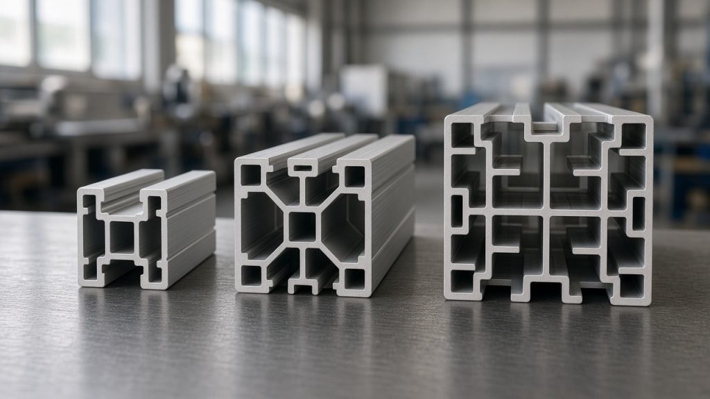
A 45 × 90 mm six-slot 6063-T5 bar weighs 4.10 kg/m with I ≈ 68 cm⁴ on the strong axis, and under EN 755-9 the wall sits within ±0.15 mm while straightness is held to 1.5 mm/m. Those numbers sit on the drawing; the slot mouth — 6 mm, 8 mm or 10 mm — decides which nut actually fits.
Short answer
Metric T-slot framing uses three mouth widths: 6 mm on the 20 series, 8 mm on most 30 and 40 series, and 10 mm on the 45 series and heavier frames. A 2020 profile is 20 × 20 mm with a 6 mm slot; European workbenches most often land on 8 mm / 40-series hardware. Choose 8 mm when M6–M8 fasteners and mid-span loads are enough; choose 10 mm when the joint needs a larger nut, a thicker lip and a heavier envelope. Copy the geometry table below into the drawing, then hold extrusion to EN 755-9 (wall ±0.15 mm, straightness 1.5 mm/m, twist 2°) and secondary cuts to length ±0.5 mm, hole position ±0.2 mm and end square within 0.3 mm.
What is the standard slot for a workbench in europe
For a European industrial workbench the default is an 8 mm slot on a 40-series envelope, because that geometry takes the M6–M8 hardware most fixture shops already stock.
Light display or lab benches sometimes drop to 20-series / 6 mm when the span is short and the load is a few tens of kilograms. Heavy welding or robot cells step up to 45-series / 10 mm so the lip and the nut can carry higher joint preload. The table maps the mouth to the series a buyer will actually find in a European catalogue; the outer size can be 30 × 30, 40 × 40, 40 × 80 or larger without changing the fastener family once the mouth is fixed.
| Use case | Typical series | Slot mouth | Usual fasteners | Verdict for a workbench |
|---|---|---|---|---|
| Light lab / display bench | 20 series | 6 mm | M3–M5 | Only if spans stay short |
| Standard assembly bench | 30 / 40 series | 8 mm | M6–M8 | European default |
| Heavy fixture / welding table | 40 / 45 series | 8 or 10 mm | M8 | Prefer 10 mm if reuse is long |
| Robot cell / gantry base | 45 / 50 series | 10 mm | M8–M10 | 10 mm slot |
| Guard frame only | 20 / 30 series | 6 or 8 mm | M5–M6 | 6 mm acceptable |
| Mixed plant standard | 40 series | 8 mm | M6–M8 | Keep one hardware kit |
What is the slot width on a 2020 profile
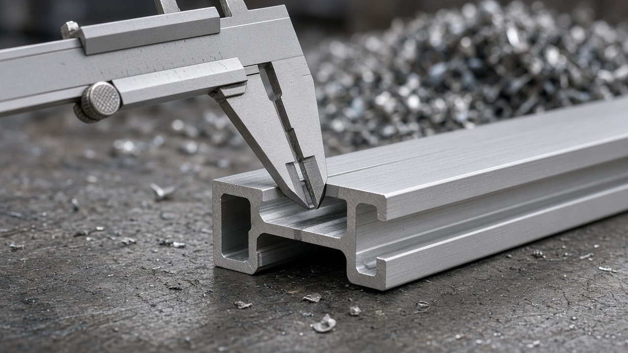
A 2020 profile is 20 × 20 mm and uses a 6 mm slot mouth; the inner channel is typically about 8 mm wide and 4.6 mm deep with a centre bore near Ø4.2 mm for an M5 tap.
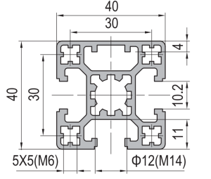
The name is the envelope in millimetres, not the slot. The same 6 mm mouth appears on 20 × 40 and 20 × 60 bars in the same family. Heavier envelopes move the mouth: 30 and most 40 series use 8 mm; 45 series uses 10 mm. Use the geometry grid below as a drawing paste-in; confirm critical fits on a sample because lip thickness and undercut vary slightly between dies even when the mouth is nominally identical.
| Series / section | Envelope | Slot mouth | Channel (typ.) | Centre bore (typ.) |
|---|---|---|---|---|
| 20 series / 2020 | 20 × 20 mm | 6.0 mm | 8.0 × 4.6 mm | Ø4.2 mm (M5) |
| 20 series / 2040 | 20 × 40 mm | 6.0 mm | 8.0 × 4.6 mm | Ø4.2 mm |
| 30 series / 3030 | 30 × 30 mm | 8.0 mm | 11.0 × 6.2 mm | Ø6.8 mm (M8) |
| 40 series / 4040 | 40 × 40 mm | 8.0 mm | 11.0 × 6.2 mm | Ø6.8 mm |
| 45 series / 4545 | 45 × 45 mm | 10.0 mm | 14.0 × 7.8 mm | Ø8.5 mm (M10) |
| 45 series / 4590 | 45 × 90 mm | 10.0 mm | 14.0 × 7.8 mm | Ø8.5 mm |
How do i choose between 8 mm and 10 mm slot profiles
Choose 8 mm when M6–M8 hardware and mid-range joint loads are enough; choose 10 mm when you need a larger nut, a thicker lip and a heavier series for long spans or repeated rebuilds.
An 8 mm mouth is the volume standard on 30 and 40 series machine frames and workstations. A 10 mm mouth appears on 45-series and many heavy 40/50 variants, and it is the safer pick when connectors stay installed for years under vibration. The outer envelope still sets bending stiffness: a 45 × 90 mm six-slot bar at 4.10 kg/m with I ≈ 68 cm⁴ out-stiffs a light 40 × 40 even before the slot is considered. Match the fastener first, then pick the envelope for span and mass. If an existing plant already standardises on one mouth, stay on that mouth so T-nuts and brackets remain interchangeable.
How to read the table
Read each row as three decisions: envelope for stiffness, mouth for hardware, and bore for end-tapping or internal anchors.
The first columns fix the outer size you draw; the mouth column fixes the nut; the bore column fixes whether an M5, M8 or M10 tap is realistic. Tolerances sit outside the geometry table: extrusion wall ±0.15 mm, straightness 1.5 mm/m and twist 2° under EN 755-9; after cutting, length ±0.5 mm, hole position ±0.2 mm and end square within 0.3 mm. Weight per metre is area × 2.70 g/cm³; the 45 × 90 example at 4.10 kg/m is the figure to put on a BOM when that section is specified. Die cost and lead time are separate commercial lines — see how die cost amortises per meter, minimum order with a new die, die making adds 7–12 days and who owns the die.
RFQ checklist — slot dimensions on the drawing
- Series and envelope — e.g. 4040 or 45 × 90 mm six-slot.
- Slot mouth — 6, 8 or 10 mm, with a measured sample if hardware is reused.
- Hardware set — T-nut size and whether core-hole anchors are used.
- Alloy / temper — usually 6063-T5 for framing.
- Mass and inertia — kg/m and I if the span is structural.
- Tolerances — EN 755-9 plus cut/hole call-outs.
Put the mouth width on the drawing next to the envelope. A 40 × 40 label without “8 mm slot” leaves the fastener ambiguous.
Related on this site
- how die cost amortises per meter — tooling share inside the metre price
- minimum order with a new die — 150 m existing vs 500 m new
- die making adds 7–12 days — calendar before first bars
- who owns the die — tooling title after the trial
Terms used in this article
- Slot mouth
- The narrow opening at the face of a T-slot; the dimension a nut must pass.
- Series
- The envelope family (20, 30, 40, 45…) that usually locks the mouth width.
- Centre bore
- The longitudinal hole used for end tapping or internal anchors.
- EN 755-9
- European extrusion tolerance standard for wall, straightness and twist on the lengths we ship.
- Moment of inertia (I)
- Section property that sets bending stiffness for a given span and load.
Questions buyers ask
What standard are the tolerances measured against?
Extrusion wall, straightness and twist follow EN 755-9: wall ±0.15 mm, straightness 1.5 mm/m and twist 2° on the lengths we ship. Cut and hole work after extrusion is held to cut length ±0.5 mm, hole position ±0.2 mm and end square within 0.3 mm. Slot mouth itself is a catalogue geometry, so quote the series and measure a sample when hardware fit is critical.
Can you supply a mill certificate?
Yes. Mill certificates for 6063-T5 (or the alloy on the order) ship with the batch and list heat number, chemistry and temper. For a drawing hand-off, ask for the certificate together with the section weight per metre so the mass on the BOM matches the invoice kilograms.
What is the minimum wall thickness?
On standard T-slot catalogue dies the thinnest wall is set by the series tooling, typically about 1.5 mm on light 20-series and thicker on 40 and 45 series. Custom dies can go thinner, but below about 1.2 mm the press window narrows and surface quality suffers. Put the critical wall on the drawing rather than assuming the catalogue minimum.
How is weight per metre calculated?
Weight per metre is cross-sectional area times density 2.70 g/cm³ for 6063, expressed as kg/m. A 45 × 90 mm six-slot section at 4.10 kg/m is the worked example on this page; Ix around 68 cm⁴ comes from the same nominal section. Use the mill mass on the certificate for freight, not a rounded catalogue figure.
Send the series and the hardware you must fit
Attach the section code or a dimensioned end view, name the T-nut or anchor you reuse, and we will confirm mouth, bore and mass against a sample before the die or cut list is locked.
Request a quoteRelated reading
Twelve more engineering notes from this blog, picked for this article — plus every category below.
 ApplicationsAluminium Profile Workbenches: Design the Top and the Frame as Two Separate Problems
 Engineering DesignWho Owns the Extrusion Die After Tooling Is Paid?
 Engineering DesignAluminium Profile Basics: What the Series Numbers and Slot Codes Mean
 Engineering Design6063 vs 6061 vs 6082 and T5 vs T6: What Changes in Practice
 Engineering DesignHow to Choose the Right Aluminium Profile Size for Industrial Frames
 Engineering DesignStandard vs Custom Aluminium Extrusion: The Break-Even Calculation
 Engineering DesignAluminium Extrusion Capacity: What a Factory Can Actually Deliver
 Engineering DesignHow to Choose an Aluminium Extrusion Profile: The Three Decisions That Bind
 Materials and Engineering6063-T5 Aluminium Profile: What the Designation Actually Guarantees
 Sourcing and ProcurementAluminium Profile MOQ: 150 m Existing Die, 500 m New
 Quality and InspectionAluminium Profile Finishes: Choose by Failure Mode, Not by Process Name
 Materials and EngineeringIndustrial Aluminium Extrusion: Five Advantages and the Conditions Attached to Each
