Quick answer
How to pick a 4040 for a machine frame
Check deflection first. A 6063-T5 aluminium beam bends long before it yields. The number that governs is the second moment of area, I, which for a standard-wall 40 × 40 mm section is about 9.8 cm⁴. Everything else follows from I, the span and the load.
Use L/300 as your working limit unless the application is stricter. A 1,000 mm span then allows 3.3 mm of sag. On a machine frame that is invisible; on a rail carrying a linear bearing it is already too much, and you should be working to L/500 or better.
Expect less than you think. A standard 4040 on a 1,000 mm span carries roughly 112 kg as a central point load at L/300 — and only about 28 kg when the span doubles to 2,000 mm, because deflection rises with the cube of the span.
Distrust any load table that is 10× more generous. Mixing kilograms and newtons is the single most common error in aluminium framing calculators. It changes the answer by 9.81, and it always errs on the dangerous side.
The governing number
What “4040” tells you, and what it does not
4040 means a 40 mm × 40 mm envelope. That is the whole of what the name tells you. It says nothing about wall thickness, slot depth, slot count or alloy, and those four variables decide whether the profile carries 30 kg or 150 kg over the same span.
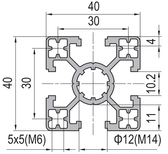
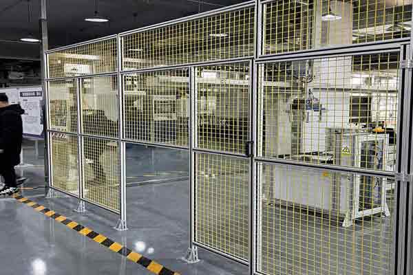
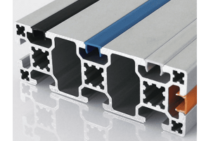
Our 4040 four-slot section is a 40 × 40 mm envelope in 6063-T5 with an M6 slot, an 8 mm slot mouth and a 30 mm slot pitch on all four faces, plus a Ø12 mm centre bore tapped M14 for through-bolting. Wall thickness is held to ±0.15 mm to EN 755-9, and the same die family runs in light, standard and heavy wall, which is why the weight is quoted as a range of 1.30 to 2.35 kg per metre rather than a single figure.
The calculation
The deflection formula and the three load cases that cover most frames
Deflection is what you check. Bending stress is almost never the binding constraint on an aluminium frame — the material would have to deflect several centimetres before it yielded, and by then the frame has already stopped doing its job.
δ = F × L³ / (48 × E × I)Simply supported beam, single central point load. δ is deflection in mm. F is the load in newtons. L is the span in mm. E is Young’s modulus, 70,000 N/mm² for 6063-T5. I is the second moment of area in mm⁴.δ = 5 × W × L³ / (384 × E × I)Simply supported beam, uniformly distributed load. W is the total distributed load in newtons, not per metre. For the same maximum deflection a distributed load allows 1.6 times the total load of a central point load.δ = F × L³ / (3 × E × I)Cantilever, point load at the free end. Sixteen times the deflection of the same load centrally on a simply supported span of the same length. A cantilever is the most expensive way to carry a load.Why the cube matters more than anything else
Span appears cubed. Doubling the span does not halve the capacity, it cuts it to one eighth. In practice you get some of that back because the allowable deflection also grows with span, leaving a net factor of about four. This is why a 4040 that feels rigid at 800 mm feels springy at 1,600 mm, and why the fix is almost always to shorten the span with a mid-support rather than to buy a bigger profile.
The tables
Allowable central point load at L/300, by 4040 wall and span
Calculated for 6063-T5, E = 70,000 N/mm², simply supported with a single central point load, deflection limited to L/300. Values are given in kilograms for convenience and derived from the newton figure, so the conversion is already done. The I values are the published section properties of our own 4040 die family, taken from the same basis so they can be compared directly.
| 4040 variant | I (cm⁴) | Weight | I per kg/m | 600 mm | 1,000 mm | 1,500 mm | 2,000 mm | 3,000 mm |
|---|---|---|---|---|---|---|---|---|
| Light wall | 7.5 | 1.30 kg/m | 5.8 | 238 kg | 86 kg | 38 kg | 21 kg | 10 kg |
| Standard wall | 9.8 | 1.70 kg/m | 5.8 | 311 kg | 112 kg | 50 kg | 28 kg | 12 kg |
| Heavy wall | 13.5 | 2.35 kg/m | 5.7 | 428 kg | 154 kg | 69 kg | 39 kg | 17 kg |
The 4040 standard figure of 9.8 cm⁴ is not published on our own 4040 page, so here is the check: our 45 × 45 mm section publishes 15.5 cm⁴, and scaling by the fourth power of the envelope — (40/45)⁴ — gives 9.7 cm⁴. The two agree to within a percent, which is the whole point of the fourth-power rule.
Read the standard row carefully, because it is the row people get wrong. A 2,000 mm span carries about 28 kg as a central point load at L/300. If your frame has a 2,000 mm unsupported rail with a 60 kg gearbox hanging on it, a standard 4040 is not the answer — and no amount of better brackets will change that.
The fourth column is worth a moment. All three walls land on the same number, about 5.8 cm⁴ of stiffness per kilogram. A heavy wall does not beat the light one on efficiency; it buys stiffness in exact proportion to the aluminium it adds. On a square section of this shape, stiffness and weight move together, which is what makes a wall change a fair late-stage fix rather than a bargain. To break out of that line you have to change the shape of the section, not its wall — a point we set out in the 4040 selection guide, where the rectangular alternatives are compared against it directly.
The unit trap that makes load tables wrong by 10×
The formula expects force in newtons. A load given in kilograms must be multiplied by 9.81 first. Skip that step and the arithmetic is internally consistent, the spreadsheet runs, and the answer is wrong by a factor of 9.81 — always in the unsafe direction. Check any published table against one row you can verify: a 4040 on a 1,000 mm span should land near 112 kg, not near 1,100 kg.
Uniformly distributed load: the case that is usually generous
Most real frame loads are distributed rather than point loads — a panel, a conveyor, a row of fixtures. For the same maximum deflection, a uniformly distributed load allows 1.6 times the total load of a central point load. The 4040 standard row becomes roughly 179 kg over 1,000 mm and 45 kg over 2,000 mm.
This is worth knowing because it is the cheapest form of capacity you can get: spreading a load along a rail instead of hanging it in the middle is free, and it buys 60%. If you are close to the limit, moving the mounting points apart is often enough.
Worked example
A 1,200 mm machine frame rail carrying a 60 kg drive unit
The drive unit sits 400 mm along a rail that is supported at both ends 1,200 mm apart. This is a near-central point load, so use the central case as a conservative check.
F = 60 kg × 9.81 = 589 NAlways convert to newtons before touching the deflection formula. This single line is where most of the errors happen.δ = 589 × 1200³ / (48 × 70000 × 98000) = 3.1 mmUsing I = 9.8 cm⁴ = 98,000 mm⁴ for a standard 4040. The span cubed is 1.728 × 10⁹ mm³.A deflection of 3.1 mm over a 1,200 mm span is L/388. That passes L/300 comfortably and sits close to L/400, so the standard 4040 works — but it does not work with much margin if the drive unit is on a linear rail that needs alignment, or if a second unit is added later.
Three ways to improve it, in order of cost:
Add a mid-support. Halving the span cuts deflection to one eighth of the raw value, or about one quarter after allowing the tighter deflection limit that comes with a shorter span. This is almost always the cheapest and best fix, and it costs one leg and two brackets.
Going from standard to heavy raises I from 9.8 to 13.5 cm⁴ and cuts deflection to 2.2 mm. Same die family, same slot geometry, same brackets, about 38% more weight. No redesign needed.
Moving to a 4060 mounted on edge raises I to about 24 cm⁴ and cuts deflection to 1.3 mm. It is 50% heavier than the 4040 per metre and 2.4 times as stiff — the best stiffness-per-kilogram trade in the range. It does change the frame geometry, the connectors and the panel details, so it is a design decision rather than a substitution.
The orientation trap on rectangular sections
Our 40 × 60 section publishes 24 cm⁴ on edge and 13 cm⁴ flat — nearly a factor of two, and the same profile. There is nothing on the outside of a rectangular extrusion to tell you which way it was meant to go once it is installed. Mark the orientation on the cut list, not only on the assembly drawing, and check the first frame before the rest are built.
Section choice
Four-slot, three-slot or two-slot — and when 4040 is not enough
| Variant | Slots | Choose it when | Watch out for |
|---|---|---|---|
| 4040 four-slot | All four faces | Machine frames, workstations, guards. The default, because every face can take a connector, a panel fixing or an accessory without machining | Nothing significant. It is the most versatile and the most widely stocked |
| 4040 three-slot | Three faces | Where one face must be flat — a sliding surface, a mounting face, or a seal face | Losing a face removes a whole plane of connector options. Check the joint design before ordering |
| 4040 two-slot | Opposite faces | Where two faces must be flush, typically a corner post that panels clamp against | Two slots is not enough for most corner joints. Usually paired with a different profile for the rails |
| 4040 light | Four faces | Short spans under 600 mm, display frames, lightweight enclosures, anything that has to be lifted often | 1.30 kg/m looks attractive until the span grows. Check the table before choosing it on weight alone |
| 4040 heavy | Four faces | Spans of 1,500 mm and over, or anywhere vibration or alignment matters | The cheapest late fix, but it does not fix a 3,000 mm span. Past that point you need a different section |
When a 4040 is the wrong answer
- Unsupported spans over about 1,800 mm with a real load. At 2,000 mm the standard section carries about 28 kg centrally at L/300. Add a mid-support or step up the section.
- Any frame that will be pushed sideways. Deflection under a vertical load and sway under a horizontal load are different problems. A 4040 frame with only bracket joints racks; bracing is the fix, not a bigger profile.
- Anywhere the frame must hold alignment. A machine tool base, a measuring fixture or a rail bed needs L/500 or better. That is a stiffness requirement, and it is met by section choice and support spacing, never by tightening the bolts harder.
- Where the weight matters more than the stiffness. If the structure is lifted, moved or shipped regularly, a light 4040 with more supports usually beats a heavy 4040 with fewer.
Specification
What to write on the order so the second batch matches
Aluminium profile is bought by the metre and specified by the name, which is exactly why two batches can differ. Put these lines on the purchase order and the profile becomes a repeatable part.
The connectors that go with this section are on the 40 series aluminium profiles page, and the matching nuts are 40 series T-nuts. If you are also choosing a larger section, the span and load method here applies unchanged to the 4060 and the 45 series range — only I changes.
Frequently asked questions
What does 4040 mean on an aluminium profile?
It is the envelope: 40 mm × 40 mm. It says nothing about wall thickness, slot depth, slot count or alloy, and those are what decide load capacity. Two profiles both sold as 4040 can differ by 50% in stiffness. Always specify the wall variant and the weight per metre alongside the envelope.
How much load can a 4040 aluminium profile carry?
It depends almost entirely on the span. At a deflection limit of L/300 with a central point load, a standard 4040 carries roughly 311 kg over 600 mm, 112 kg over 1,000 mm, 50 kg over 1,500 mm and 28 kg over 2,000 mm. The profile is the same in every case; only the span changes. A distributed load allows about 1.6 times those figures.
Why do different suppliers give different load ratings for the same 4040?
Three reasons: different wall thickness, different deflection criteria, and unit errors. Wall thickness changes I by 50% or more within the same envelope. A table calculated at L/200 will look 50% stronger than one at L/300. And a table that treats kilograms as newtons is 9.81 times too generous. Ask for the wall, the deflection limit and the units before comparing anything.
Is a 4040 strong enough for a machine frame?
For strength, almost always yes — aluminium framing fails by deflection, not by yielding. For stiffness, it depends on the span and the alignment requirement. Under about 1,000 mm with moderate loads a standard 4040 is fine. Beyond about 1,800 mm, or where a rail bed or fixture must hold alignment, add a mid-support or move to a heavier or larger section.
Should I choose a 4040 or a deeper section for a long rail?
A 40 × 60 mm section on edge gives about 24 cm⁴ against the 4040’s 9.8 — roughly two and a half times the stiffness for half again the weight. For a long unsupported rail that is the better answer. The catch is orientation: mounted flat, the same 4060 drops to about 13 cm⁴ and loses nearly half its advantage. If the rail is under about 1,500 mm, adding a mid-support to a 4040 is usually cheaper and keeps the frame geometry unchanged.
How do I convert kilograms to newtons for the deflection formula?
Multiply by 9.81. A 60 kg load is 589 N. The deflection formulas expect force in newtons, E in N/mm² and lengths in millimetres, so the result comes out in millimetres with no further conversion. Reporting a newton result as kilograms is the most common error in aluminium framing tables and it overstates capacity by a factor of 9.81.
Send us the span and the load
Give us the unsupported span, the load and the deflection you can tolerate. We will come back with the wall variant, the section and the support spacing that meet it, extruded to EN 755-9.
Related reading
Twelve more engineering notes from this blog, picked for this article — plus every category below.
 ApplicationsAluminium Pergola Profiles: A Beam Problem With a Water Problem
 Engineering DesignAluminium vs Steel, Extruded vs Cast: What Actually Changes
 Engineering DesignAluminium Extrusion Price per Meter: How the Number Is Built
 Engineering DesignStandard vs Custom Aluminium Extrusion: The Break-Even Calculation
 Engineering DesignESD Anti-Static Workbench Grounding: The Four Joints That Break the Path
 Engineering DesignWhich Profile Size for Your Application: A Selection Guide
 Engineering DesignAluminium Extrusion Tolerances: What to Write, and How to Inspect
 ApplicationsAluminium Profile Display Boards: The Panel Is the Hard Part
 Sourcing and ProcurementDistributor Terms: Territory, Margin and Price Protection
 ApplicationsESD-Safe Aluminum Profile Workbenches: Why Anodising Alone Fails the Audit
 Quality and InspectionAluminium Profile Finishes: Choose by Failure Mode, Not by Process Name
 ApplicationsCleanroom and Medical Framing: There Is No Medical-Grade Aluminium Extrusion
