Quick answer
Five steps, and the order matters
1. Write the load case, not the load. A point load at mid-span and the same load spread along the beam are different structures. So are a static load and a moving one.
2. Write the unsupported span. Not the frame width. The distance between the two nearest rigid supports. Deflection rises with the cube of this number, which makes it the most powerful variable you control.
3. Write the deflection budget. L/300 is a reasonable default for a machine frame. It is not good enough for a linear guide rail, where you want L/500 or better, and it is generous for a guard panel that carries nothing.
4. Calculate the second moment of area you need. One line of arithmetic gives I required in cm⁴. That number, not a catalogue category, is what you shop with.
5. Pick the smallest section that clears it, then change the span if none does. If the required I is bigger than any square section in your accessory system, the answer is almost never a bigger square. It is a mid-support or a rectangular section used on edge.
The lever that matters most
Change the span before you change the profile
Almost every profile-selection conversation starts with the section and ends with a support being added anyway. Reverse that order and the whole exercise gets cheaper. The reason is the exponent: deflection is proportional to the cube of the span, and only to the first power of the load. Halving a span cuts the deflection of a given load to one eighth. Halving the load cuts it to one half.
In practice you do not get the full factor of eight, because the allowable deflection also scales with the span — a shorter beam is allowed to sag less in absolute terms. Working to L/300 throughout, halving the span gives you back a factor of about four in allowable load. That is still the largest single gain available anywhere in this decision.
Two consequences follow, and they are worth stating plainly because they contradict how most frames are specified:
- A mid-support is usually cheaper than a bigger section. One extra upright in a 40 series frame adds roughly 1.5 kg of profile and four brackets. Stepping the whole beam from 40 × 40 to 60 × 60 adds 2.6 kg per metre and forces every nut, bracket and panel fixing in that joint to change with it.
- Beam size should be the last thing you scale, not the first. If the frame is still too springy after the spans are as short as the layout allows, you have a genuine section problem and the numbers below will tell you which section solves it.
Load case
Where the load sits changes the answer by five times
Suppliers publish one load figure per profile, and it is always the mid-span central point load, because that is the worst case and the easiest to calculate. Real frames rarely load the middle. A drive unit sits at one end of a rail. A cylinder pushes at a third of the way along. Two brackets carry a panel between them. Each of those is a different beam problem, and the differences are large enough to change which section you buy.
For a simply supported span, a point load of F at distance a from one support deflects the beam at the load point by:
δ = F × a² × b² / (3 × E × I × L)a is the distance from the left support to the load, b is L minus a, L is the span. Set a equal to b equal to half the span and this collapses to the familiar F·L³/(48·E·I).Put the load at the quarter point instead of the middle and the deflection falls to nine sixteenths of the mid-span value — a 44 per cent saving for free. Put it at the eighth point and it falls to under a fifth. This is why the honest answer to “what does a 4040 carry over one metre” is a range, not a number.
| Load case | Deflection factor | What it means in practice |
|---|---|---|
| Single central point load | 1.00 | The published figure. The worst arrangement that is still symmetric. |
| Two equal loads at the quarter points | 0.69 | Two bearings or two feet sharing the same total load. Cheaper than the mid-span case by a third. |
| Uniformly distributed load | 0.63 | A panel, a table top, a shelf, a cable tray. For the same total weight it deflects 37 per cent less than a point load. |
| Single point load at a quarter point | 0.56 | The drive unit at one end of a rail. Nearly half the deflection of the same load in the middle. |
| Single point load at an eighth point | 0.19 | Load right beside an upright. Effectively a joint problem, not a beam problem. |
| Cantilever, load at the free end | 16.0 | A bracket arm or an overhanging rail. Sixteen times the mid-span case for the same load and length. |
The one that catches people out
A cantilever is not a slightly worse beam, it is a completely different structure. If your load hangs off the end of an overhanging member, everything on this page is off by a factor of sixteen and you should be designing that member as a cantilever with the deflection calculated at the free end. In practice this is the reason overhanging control-panel arms and cantilevered sensor rails use rectangular sections on edge rather than a heavier square.
The budget
Set the deflection budget before you calculate anything
Deflection only becomes a pass or fail once you have decided how much sag the application tolerates. That is an application decision, not an engineering one, and it is the step most selection guides skip — which is why they end up saying “choose a larger profile” without ever saying how much larger.
The usual convention is a fraction of the span, because a short beam should be allowed less absolute sag than a long one. As a starting point:
| Application | Working limit | Why that limit |
|---|---|---|
| Guards, covers, enclosures | L/200 | Nothing measures position against the frame. You are only stopping visible flex and panel rattle. |
| General machine frames and workbenches | L/300 | The default. A 1,000 mm member may sag 3.3 mm and nobody notices. |
| Frames carrying a linear guide or a rail bed | L/500 | Rail sag is directly transferred into the carriage. Sag is no longer cosmetic, it is a positioning error. |
| Measuring fixtures and metrology frames | L/1,000 or an absolute figure such as 0.1 mm | Below about L/1,000 the frame stops being the dominant error source and thermal movement takes over. |
| Safety structures in an impact path | Not a deflection question | Impact energy, not stiffness, decides these. Sizing them from a deflection table is a category error. |
Two notes on using this table. First, the limit applies to the worst-loaded member, not to the frame as a whole. A workbench can be a general L/300 structure while the one rail that carries a guide is held to L/500. Second, if the frame will be levelled on a floor that is itself flat only to a few millimetres, holding a beam to 0.2 mm of calculated sag is measuring the wrong thing.
The tolerance on E, and on the temper claim
Young’s modulus for 6063 is about 70,000 N/mm² — 70 GPa — and it is essentially the same for T5 and for T6. Temper changes yield strength, hardness and how the section anodises; it does not change stiffness. A supplier who offers T6 “so the frame will be stiffer” is describing a real material upgrade for the wrong reason. If your design is deflection-limited, T5 and T6 perform identically. If it is strength-limited, T6 buys you roughly a 40 per cent higher yield point and that is worth having.
Strength or stiffness
Which limit binds depends on the span
Every aluminium framing guide talks about deflection. Almost none of them mentions the other limit, and on short spans the other limit is the one that governs. An aluminium beam can fail in two distinct ways: it can bend too far (a stiffness limit, set by the geometry of the section) or it can yield at the extreme fibre (a strength limit, set by the alloy). They cross over at a specific span, and on a 40 × 40 mm standard section that crossover is almost exactly one metre.
The strength check is short. Bending stress is the moment divided by the section modulus, and the section modulus is the second moment of area divided by half the section depth:
σ = M / S S = I / c M = F × L / 4For a 40 × 40 mm standard wall section, I is about 9.5 cm⁴ and c is 20 mm, so S is about 4,750 mm³. Taking 6063-T5 yield as 110 MPa and applying a safety factor of 2.0 gives an allowable stress of 55 MPa, and therefore an allowable moment of about 261 N·m.Run both checks across the span range and the picture becomes clear:
| Span | Limit from deflection, L/300 | Limit from yield, safety factor 2.0 | Which one binds |
|---|---|---|---|
| 600 mm | 301 kg | 178 kg | Strength — by a wide margin |
| 800 mm | 169 kg | 133 kg | Strength |
| 1,000 mm | 108 kg | 107 kg | Both, at the same load |
| 1,200 mm | 75 kg | 89 kg | Deflection |
| 1,500 mm | 48 kg | 71 kg | Deflection |
| 2,000 mm | 27 kg | 53 kg | Deflection — by a factor of two |
| 3,000 mm | 12 kg | 36 kg | Deflection — by a factor of three |
Read the table from the left and two things happen at once. Below a metre, a 4040 does not fail because it bends too much — it fails because the aluminium at the top and bottom of the section reaches its yield point. Above a metre, the yield check becomes irrelevant and the whole design is a stiffness exercise. The crossover for this section sits at about 1,020 mm.
That single number explains a lot of field experience. It explains why short, heavily loaded brackets sometimes deform while long, lightly loaded rails simply sag. It explains why the answer to “how much does a 4040 hold” is not one number but a curve. And it explains why raising the alloy temper helps a stubby bracket but does nothing at all for a four-metre rail.
What this means when you specify
If your longest span is under about a metre, ask for the alloy and temper to be certified, because you are buying strength. If it is over about a metre, the temper is nearly irrelevant and what you need on the drawing is the second moment of area and the wall thickness, because you are buying stiffness. Buying the wrong one of those two things is the most common way to pay for a section that still does not work.
The method
The five-step selection sequence
This is the whole method, in the order that produces a decision. It takes about ten minutes with a calculator and it replaces the catalogue-browsing loop that usually consumes an afternoon.
Convert to newtons — kilograms multiplied by 9.81 — and then apply the appropriate dynamic factor. Use 1.0 for a genuinely static dead load, 1.5 to 2.0 for anything driven by a pneumatic cylinder or stopped by a bumper, and 3.0 for a load that can be dropped or impacted. Multiply the result by 1.6 if you want to compare it against a distributed-load table, because a distributed load of the same total weight only deflects 63 per cent as much.
Measure between the two nearest rigid supports, centre to centre of the uprights. Do not use the frame width. If a joint in the middle of the member is held by brackets only, treat the whole length as unsupported — a bracket joint carries moment poorly, and assuming it acts as a support is the second most common cause of an under-designed frame.
Span divided by 300, or by whatever limit the application table above gives you. A 1,200 mm span at L/300 means 4 mm.
Rearrange the deflection formula. This gives you a single number in cm⁴ to shop with, and it is comparable across every supplier and every section shape.
If the required I is larger than anything reasonable in your accessory system, do not keep climbing the ladder. Halve the span instead and re-run step four. Only if the layout genuinely forbids a support should you accept a big section or a rectangular one on edge.
I required = F × L³ / (48 × E × δ)F in newtons, L in millimetres, E is 70,000 N/mm², δ is your allowable deflection in millimetres. The answer comes out in mm⁴; divide by 10,000 to get cm⁴. This is the simply supported central point load case. For a distributed load replace 48 with 76.8, which is the same as dividing the required I by 1.6.A shortcut worth memorising
Working to L/300 with E equal to 70,000, the whole formula collapses into one line: allowable central point load in kilograms is 1.14 × 10⁷ × I in cm⁴ divided by the span in millimetres squared. Learn that and you can size a frame member in your head at a meeting. It also means that when someone hands you a load figure with no span attached, you can ask the only question that matters: over what distance?
The ladder
Turning your required I into a part number
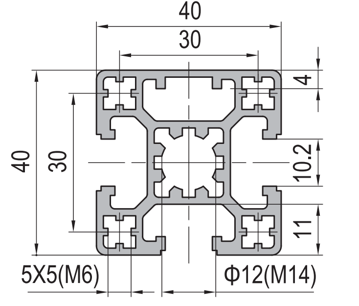
Step four gives you a single number: the second moment of area your member needs, in cm⁴. The table below converts that number into a section, which is the last step of the method and the only step most guides describe. Read down the left column until you find your required I, then read across. Every section named here is drawn and published in our aluminium sections range, and the four-slot 4040 that most machine frames land on is here.
| Required I | Smallest square section that clears it | Smallest rectangular option | What to watch |
|---|---|---|---|
| Under 1 cm⁴ | 20 × 20 single slot | none available | Only for short spans and light covers. Check the slot takes the fastener you need |
| 1 to 4 cm⁴ | 20 × 40 two slot, or 30 × 30 standard | none available | The two-slot section gives one strong axis only, so brace the other direction |
| 4 to 8 cm⁴ | 30 × 30 standard | none available | Below about 8 cm⁴ the yield limit usually governs rather than deflection |
| 8 to 15 cm⁴ | 40 × 40 standard | 40 × 60 used flat | The default range. Check the joint as well as the member at this level |
| 15 to 25 cm⁴ | 45 × 45 standard | 40 × 60 used on edge | The rectangular option is the better buy here: same weight per metre as 45 series, more stiffness |
| 25 to 40 cm⁴ | 60 × 60 standard, then heavy wall | 45 × 60 used on edge | You are now in the range where a mid-support is almost always cheaper than the section |
| 40 to 150 cm⁴ | 50 × 100 used flat | 50 × 100 used on edge | Check the depth fits the machine envelope before you commit to a 100 mm section |
| Over 150 cm⁴ | no single section solves it economically | two members, or a support | Halve the span and re-run step four. This is where the calculation is telling you to change the geometry |
Three things this presentation makes obvious that a load table does not. First, the table is a lookup, not a comparison — you do not need to know what every section carries, only which one clears your number. Second, the rectangular column is often better than the square one at the same level, which is why the shape of a member is worth deciding before the size. Third, the last row exists at all: there is a point past which no single section is the right answer, and the calculation is telling you so.
If two rows both look plausible
Take the smaller section and check the yield limit from the section above. Below about a metre of span, the strength limit usually binds before the deflection limit, and it is set by the alloy and the section modulus rather than by the second moment of area. A section that passes the deflection check can still fail the strength check on a short, heavily loaded member — which is exactly the trap the next table covers.
Before you take the rectangular option
A rectangular section only resists bending well in one direction. If you choose one because it clears the required I at a lower weight, check the other axis as well — the frame has to be braced against sideways load whatever the member does vertically. A rectangular beam that is stiffer than the square it replaces, in a frame that racks, is not an improvement.
Worked example
A 2,000 mm frame, sized two ways
Here is the whole method applied to a real problem. A control cabinet weighing 90 kg is to be mounted on a cross rail between two uprights 2,000 mm apart. The rail must not visibly flex when the door is opened, so the client has asked for L/300.
Enlarge the section
Load: 90 kg × 9.81 = 883 N, static, so no dynamic factor. Span: 2,000 mm. Budget: 2,000 / 300 = 6.67 mm.
I required = 883 × 2,000³ / (48 × 70,000 × 6.67) = 31.5 cm⁴.
Nothing in the square range reaches 31.5 cm⁴ except the 60 × 60 heavy at 38. A 50 × 100 on edge would work at 150 cm⁴ but is grossly over-sized and 6.2 kg/m.
Halve the span
Same load, one extra upright in the middle. Span: 1,000 mm. Budget: 1,000 / 300 = 3.33 mm.
I required = 883 × 1,000³ / (48 × 70,000 × 3.33) = 7.9 cm⁴.
A 40 × 40 standard section at 9.5 cm⁴ clears it. Check the yield limit as well: the moment is 883 × 1,000 / 4 = 220,750 N·mm against an allowable 261,000 N·m, so the safety factor is about 2.2. It passes both checks.
The two options are not close. Option A uses a 2,000 mm length of 60 × 60 heavy wall at 6.4 kg/m, plus brackets sized for a 60 series slot. Option B uses a 2,000 mm length of 40 × 40 standard at 1.7 kg/m, plus a 900 mm upright at 1.7 kg/m, plus one extra set of brackets. In kilograms of aluminium that is 12.8 kg against 4.9 kg — and the second option also keeps the entire frame in one accessory system, one nut part number and one torque figure.
The only question that decides between them is whether the middle of the frame is allowed to have an upright in it. If the cabinet needs a clear 2,000 mm opening for access, Option A is correct and you should buy the 60 × 60 heavy wall with confidence, having proved it rather than guessed it. If the upright can go in, Option B is cheaper, lighter and stiffer in every direction except the one you did not need — and it keeps the frame on the 40 × 40 four-slot section and the accessory range that goes with it.
The general form of this result
Whenever a required I comes out larger than the top of your square-section ladder, re-run the calculation at half the span before you order anything. The required I falls by a factor of four when you halve the span at constant deflection limit, and a support rarely costs a quarter of the beam it saves.
When size is not the problem
Four symptoms that a bigger profile will not fix
Frames are often re-specified to a larger section when the real fault lies elsewhere, and the larger section then hides the fault rather than removing it. These four symptoms each have a different cause, and each one has a cheaper fix than buying aluminium.
The frame racks sideways
If the frame moves into a parallelogram when you push it from the side, you have a bracing problem. Every member in the frame is fine in bending; what is missing is a triangular load path. A diagonal, a bolted panel, or a properly fixed rigid top turns the rectangle into two triangles and removes the movement entirely. Enlarging the beams does almost nothing, because the load is not travelling down them.
The corner rotates under load
If the movement appears at a joint rather than along a member, the joint is the mechanism. Two bolts in a corner bracket resist rotation by friction and bolt bearing, and the section behind them only helps in proportion to how far apart the bolts are. A flat joining plate across the joint, or a gusset that puts the fixing further from the corner, does more than any increase in profile size.
The whole frame vibrates
Vibration is a natural-frequency problem, not a strength or stiffness problem in the usual sense. Making every member heavier lowers the natural frequency, which can move the structure closer to the excitation rather than further from it. The fixes are to stiffen the specific member that is moving, to change the mass distribution, or to damp the structure — not to upsize everything uniformly.
The load is carried by a panel, not by the frame
A frame with a thin bolted-on panel behaves as a frame plus a diaphragm. If the panel is fixed with too few fasteners it contributes nothing and the frame carries everything; if it is fixed properly it can contribute more than the members do. Getting the panel fixing right is often the difference between a frame that feels solid and one that does not, with no change of profile at all.
Questions
Frequently asked questions
Is a bigger aluminium profile always stronger?
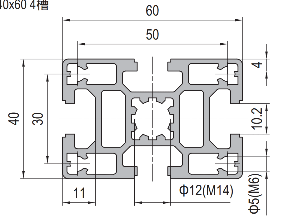
No, and the reason is usually orientation rather than size. A 40 × 60 mm rectangular section gives about 24 cm⁴ with the 60 mm face vertical and about 13 cm⁴ with it horizontal — the same section, the same weight, half the stiffness. A 50 × 100 used flat drops from about 150 cm⁴ to about 50. Beyond that, a larger section does not help at all if the movement is coming from a joint, from racking or from the base rather than from bending in the member.
What deflection limit should I design an industrial frame to?
L/300 is a sound default for machine frames, workbenches and general structures. Use L/200 for guards and covers where nothing measures position against the frame, L/500 or better for any member that carries a linear guide or a rail bed, and an absolute figure such as 0.1 mm for measuring fixtures. Apply the limit to the worst-loaded member rather than to the frame as a whole, and remember that a floor flat only to a few millimetres makes a 0.2 mm calculation meaningless.
Does 6063-T6 make a frame stiffer than 6063-T5?
No. Young’s modulus is about 70,000 N/mm² for both tempers, and stiffness depends on that modulus and on the section geometry, not on the yield strength. What T6 changes is the yield point, roughly from 110 MPa to 170 MPa. That matters on short spans and in brackets, where the design is limited by the alloy rather than by deflection, and it makes no measurable difference to a long beam.
How do I size a profile for a moving or dynamic load?
Multiply the static load by a dynamic factor and then treat it as static. Use 1.0 for a genuine dead load, 1.5 to 2.0 for loads driven by a pneumatic cylinder or stopped by a buffer, and 3.0 for anything that can be dropped or struck. For a reversing load, check the joints separately as well, because a reversing moment works fasteners loose in a way a static load does not.
Can I mix profile sizes within one frame?
Yes, and you usually should. Columns and beams do different jobs: a column resists buckling and carries vertical load, so it is sized on compression area and second moment of area, while a beam is sized on deflection. A common and efficient layout is 60 series columns with 40 series beams, or 40 × 60 sections used on edge for the long horizontal members. What you should not mix is the slot system, because every nut and bracket part number changes with the series.
How do I know the span to use if a member has a joint in the middle?
Treat the whole length as unsupported. A bracket joint between two profiles carries moment poorly, and assuming it acts as a support is one of the most common causes of an under-designed frame. If the joint must act as a support, use a flat joining plate sized to carry the moment and verify it as a connection rather than assuming the geometry does the work.
Send us the load, the span and the budget
Give us those three numbers and we will come back with the section, the wall and the accessory list — or tell you that a mid-support is the cheaper answer.
Related reading
Twelve more engineering notes from this blog, picked for this article — plus every category below.
 Engineering DesignAluminium Extrusion Capacity: What a Factory Can Actually Deliver
 ApplicationsAluminium Workbench Fit-Out: When the Accessories and the Joints Compete for the Same Slot
 Engineering DesignWhat Your Extrusion Drawing Must Show (and What Costs You Money)
 Engineering DesignAluminum vs Steel Machine Frames: Choose by Deflection, Not by Strength
 Materials and EngineeringIndustrial Aluminium Extrusion: Five Advantages and the Conditions Attached to Each
 Engineering DesignAluminium Extrusion Lead Time: New Die vs Existing Die
 Engineering DesignAluminium Extrusion Price per Meter: How the Number Is Built
 ApplicationsAluminium Profile for LED Strips: A Heat Sink First, a Housing Second
 Quality and InspectionSampling and First Article Approval for Aluminium Extrusion
 Sourcing and ProcurementImporting Aluminum Profiles from China: Nine Failures That Quietly Raise Your Landed Cost
 ApplicationsAluminium Profile Fish Tank Frames: Glass Load, Salt Water, and the Alloy Question
 Sourcing and ProcurementAluminium Profile MOQ: 150 m Existing Die, 500 m New
