Profile sizes · what fails first
Aluminium Profile Sizes 20 × 20 to 100 × 100: What Fails First
The number in the name is not the stiffness. A 50 × 50 and a 60 × 60 standard section are 4 per cent apart in second moment of area and 39 per cent apart in weight. Here is what each size actually carries, what breaks first at each step, and the four alternatives to going up a size that are usually cheaper.
Quick answer
- Size is a poor proxy for stiffness. A 50 × 50 gives about 25 cm⁴ at 3.10 kg/m; a 60 × 60 standard gives about 26 cm⁴ at 4.30 kg/m. Four per cent more stiffness for 39 per cent more weight.
- Wall thickness matters as much as the envelope. A 40 × 40 comes in light, standard and heavy walls at about 6.1, 9.2 and 12.4 cm⁴ — a factor of two inside one name, at 1.30 to 2.35 kg/m.
- Orientation can beat size. A 30 × 120 deep beam gives about 115 cm⁴ on edge and 12 cm⁴ flat — a 9.6 times difference from the same part.
- The deep beam sections are the efficiency outliers. A 30 × 120 delivers about 37 cm⁴ per kg/m on edge, against about 5.3 for a 40 × 40 standard and about 8 for a 50 × 50.
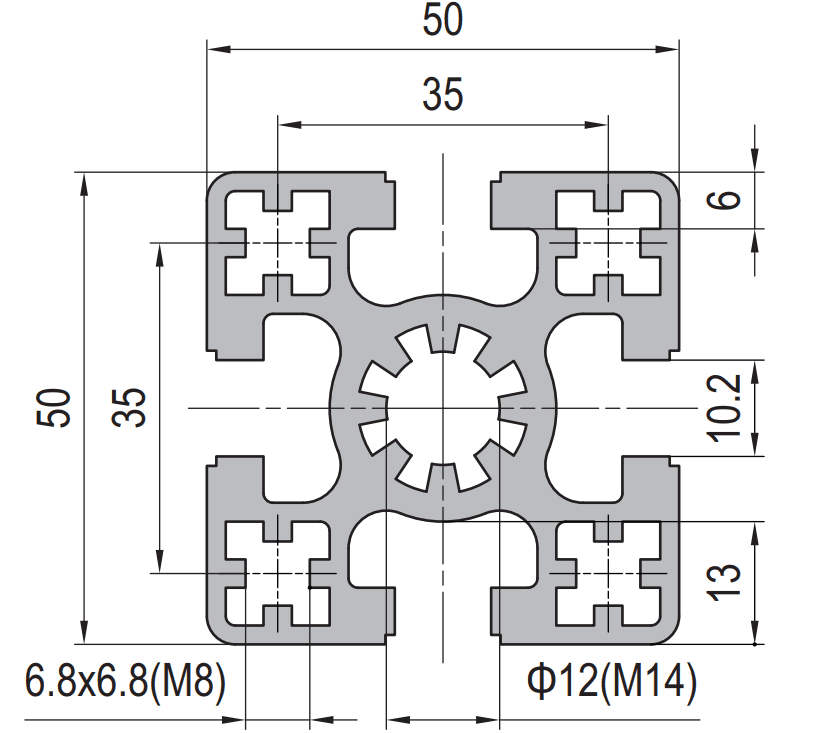
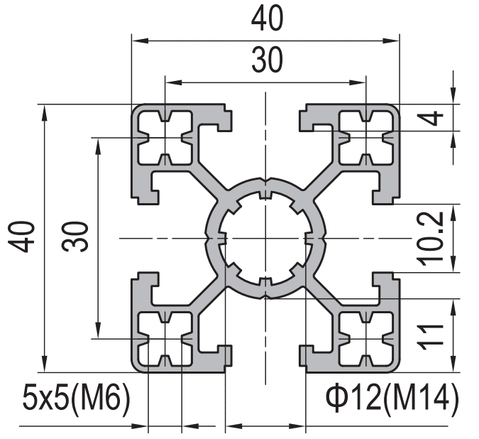
- Bigger is not always a bigger slot. The 50 × 50 has a 6.8 mm slot mouth; the smaller 40 × 40 has an 8.0 mm mouth. A bigger profile can take smaller hardware.
- Above about 60 mm, the binding constraint stops being strength. It becomes mass, cost, handling and tolerance — EN 755-9 loosens to ±0.90 mm once the circumscribing circle passes 100 mm.
Also searched as aluminium profile sizes, 20x20 to 100x100 aluminium profiles, aluminium profile size chart, t-slot profile dimensions, aluminium extrusion sizes guide, 40x40 45x45 60x60 profile comparison.
Two sections that are four per cent apart
Start with the pair that destroys the assumption behind most size charts. Take a 50 × 50 four-slot section and a 60 × 60 four-slot standard section, both in 6063-T5, both from the same extrusion house.
| Member | I (cm⁴) | Weight, kg/m | Slot mouth | Slot pitch | I per kilogram per metre |
|---|---|---|---|---|---|
| 50 × 50 four-slot | approx. 25 cm⁴ | approx. 3.10 kg/m | 6.8 mm | 35 mm | 8.1 |
| 60 × 60 four-slot | approx. 26 cm⁴ | approx. 4.30 kg/m | 10.2 mm | 48 mm | 6.0 |
| 60 × 60 four-slot heavy | approx. 38 cm⁴ | approx. 6.40 kg/m | 10.2 mm | 48 mm | 5.9 |
The 60 × 60 is a bigger member by every outside measurement, and it is barely stiffer than the 50 × 50. It weighs 39 per cent more, it costs more per metre, and it moves the whole frame into a heavier class of brackets, feet and end caps. What you are actually buying at 60 mm is not stiffness. It is the 10.2 mm slot mouth, the 14 × 14 mm internal groove, the 48 mm pitch and the larger centre bore — access, fastener size and cable routing.
The one question that replaces the size chart
Ask what the section is made of, not how big it is. Two numbers carry almost all of it: the second moment of area about the axis that matters, and the slot mouth. Everything else in a size chart — “light duty”, “heavy duty”, “medium” — is a description of those two numbers in words.
The three numbers that decide, and the one that gets forgotten
Four things move the load a profile can carry, in this order of influence: the depth of the section, the wall thickness, how the material is distributed relative to the neutral axis, and which way round you install it.
Depth dominates because stiffness scales with roughly the fourth power of it, which is why stepping from a 30 to a 40 series is worth more than any wall change inside either. Wall thickness comes second and is invisible in the name — a “4040” is three different products. Material distribution is what separates a T-slot profile from a plain tube: the slot walls and the centre boss put metal where it resists bending, at the cost of a thinner outer flange.
Orientation is the one that gets forgotten, and it can be worth more than a size change. Rectangular and deep beam sections have two very different inertias, and the gap is much wider than most people expect.
| Member | I on the strong axis | I on the weak axis | Ratio | Weight |
|---|---|---|---|---|
| 40 × 60 four-slot | approx. 24 cm⁴ (on edge) | approx. 13 cm⁴ (flat) | 1.85 × | approx. 2.55 kg/m |
| 45 × 60 four-slot | approx. 31 cm⁴ (60 mm axis) | approx. 21 cm⁴ (45 mm axis) | 1.48 × | approx. 3.30 kg/m |
| 30 × 120 three-slot | approx. 115 cm⁴ (in plane) | approx. 12 cm⁴ (flat) | 9.6 × | approx. 3.10 kg/m |
| 50 × 100 two-slot heavy | approx. 150 cm⁴ (vertical) | approx. 50 cm⁴ (horizontal) | 3.0 × | approx. 6.20 kg/m |
A 30 × 120 installed the wrong way round is a 12 cm⁴ member — worse than a 45 × 45 standard — and it weighs 3.10 kg/m. Installed the right way round it is a 115 cm⁴ beam, better than a 60 × 60 heavy at half the weight. Nothing about the part changes. Only the drawing does.
What each size carries, at three spans
The table below is a single simply supported member carrying a point load at mid-span, with the deflection limited to L/300 — the usual limit for machinery, guarding and conveyors. The three load columns are allowable load in kilograms at a 1 m, 1.5 m and 2 m span. A factor of four on the span costs a factor of eight on the load, because deflection goes with the cube.
Where the table comes from
P = 48 · E · I · δ / L³, δ = L / 300, E = 70,000 N/mm²Which reduces to about 11.4 kg per cm⁴ at a 1 m span, 5.1 kg per cm⁴ at 1.5 m and 2.9 kg per cm⁴ at 2 m. Use it to sanity-check any figure below against a member you already have.
| Member | I (cm⁴) | Weight, kg/m | At a 1 m span | At 1.5 m | At 2 m | I per kg/m |
|---|---|---|---|---|---|---|
| 20 × 20 four-slot | 1.0 | 0.90 | 11 | 5.1 | 2.9 | 1.1 |
| 30 × 30 standard | 3.6 | 1.15 | 41 | 18 | 10 | 3.1 |
| 40 × 40 light | 6.1 | 1.30 | 70 | 31 | 17 | 4.7 |
| 40 × 40 standard | 9.2 | 1.75 | 105 | 47 | 26 | 5.3 |
| 40 × 40 heavy | 12.4 | 2.35 | 141 | 63 | 35 | 5.3 |
| 40 × 60, on edge | 24 | 2.55 | 274 | 122 | 69 | 9.4 |
| 45 × 45 light | 10.5 | 1.90 | 120 | 53 | 30 | 5.5 |
| 45 × 45 standard | 15.5 | 2.55 | 177 | 79 | 44 | 6.1 |
| 45 × 45 heavy | 19.5 | 3.15 | 222 | 99 | 56 | 6.2 |
| 45 × 60, on the 60 mm axis | 31 | 3.30 | 353 | 157 | 89 | 9.4 |
| 50 × 50 four-slot | 25 | 3.10 | 285 | 127 | 71 | 8.1 |
| 60 × 60 standard | 26 | 4.30 | 296 | 132 | 74 | 6.0 |
| 60 × 60 heavy | 38 | 6.40 | 433 | 193 | 109 | 5.9 |
| 30 × 120, in plane | 115 | 3.10 | 1,311 | 583 | 329 | 37.1 |
| 50 × 100 heavy, vertical | 150 | 6.20 | 1,710 | 760 | 429 | 24.2 |
Two patterns fall out of the last column. The first is that efficiency falls as the member grows: a 20 × 20 gives 1.1 cm⁴ per kilogram per metre, a 40 × 40 standard gives 5.3, and a 60 × 60 heavy gives 5.9 for three and a half times the weight. The second is that the deep beam members break the pattern completely. A 30 × 120 on edge gives 37 cm⁴ per kilogram per metre — seven times the efficiency of a 40 × 40 standard — because depth, not material, is what buys stiffness.
Read the load figures as a comparison, not a certificate
These are simply supported mid-span figures at L/300 for a bare member in 6063-T5. They ignore the joints, the self-weight of the frame, the eccentricity of the load, torsion from an off-axis bracket, and any reversing component. A real frame is a system, and the joint usually gives up before the member does.
What fails first at each size
Every step up the range has a characteristic failure mode. Knowing which one you are buying your way out of is more useful than knowing the load number, because the failure is what the customer sees.
Joint slip and torsional wind-up
The member is 20 mm and the slot takes a slice out of every face, leaving thin flanges and a small lip bearing area. A bracket offset from the neutral axis twists the member, and a 20 series extrusion resists torsion very poorly. Fails first at: any off-axis load, any vibrating application, any unsupported length over about 0.8 m.
Deflection, then lip damage
Useful up to about 1.2 m for light loads, and it takes M5 and M6 hardware with a torque ceiling around 6 N·m. Over-torquing deforms the slot lips, which then will not hold a nut square. Fails first at: a 1.2 m unsupported length carrying more than about 18 kg, or a wrench used without a torque setting.
Deflection at long spans
The industry default, with an 8 mm mouth and a 30 mm pitch, and the widest accessory availability in the market. At a 2 m span a regular wall carries about 26 kg at L/300 — less than one control cabinet. Fails first at: a 2 m span, or any member carrying more than about 25 kg without an intermediate support.
The cross-series trap
Structurally a good step: about 68 per cent more inertia than a 40 × 40 standard for about 46 per cent more weight. Its real failure is commercial — the 10 mm mouth and 33 mm pitch mean nothing from the 40 series fits, so the accessory catalogue has to be bought again. Fails first at: a project that assumed 40 series hardware would carry over.
The smaller mouth
About 25 cm⁴ at 3.10 kilograms per metre, the best value in the middle of the range. But its slot mouth is 6.8 mm, narrower than the 8.0 mm on a 40 × 40, so it takes M8 rather than M10 hardware and no 40 series nut or bracket crosses over. Fails first at: a specification that assumed a bigger profile takes bigger fasteners.
Mass
You buy the 10.2 mm mouth, the 14 × 14 mm groove, the 48 mm pitch and the larger bore. The regular wall is only 4 per cent stiffer than a 50 × 50 while weighing 39 per cent more. Fails first at: a weight budget, a handling limit, or a cost target — not at a load.
Cost, handling and tolerance
At this size the member is chosen for the anchorage, the bore or the bending moment at a support, not for the span. Two people to handle one length, a lifting plan for an assembly, and a tolerance that has widened: EN 755-9 gives ±0.90 mm once the circumscribing circle passes 100 mm, against ±0.50 mm at 40 mm.
Installed the wrong way round
A 30 × 120 on edge is a 115 cm⁴ beam; flat it is 12 cm⁴. The failure mode is not structural, it is a drawing error — a member that was sized on edge and installed flat, or a bracket that forces the weak axis into the load path. Fails first at: the first drawing review you skip.
The upgrade ladder, priced in stiffness per kilogram
Steps up the series are not equally valuable, and the difference is large enough to plan around. This is the same table as before, rearranged as a ladder.
| Step | I gain | Weight gain | Verdict |
|---|---|---|---|
| 20 → 30 | 3.6 × | 1.28 × | Excellent. The biggest return in the range for the least weight. |
| 30 → 40 light | 1.7 × | 1.13 × | Good, and it brings the 8 mm slot and the M8 hardware class. |
| 40 light → 40 standard | 1.51 × | 1.35 × | Fair. Same envelope, same accessories, more material. |
| 40 standard → 45 standard | 1.68 × | 1.46 × | Good, and it brings the 10 mm mouth — but a new accessory catalogue. |
| 45 standard → 50 standard | 1.61 × | 1.22 × | The best step in the middle of the range on a weight basis. |
| 50 standard → 60 standard | 1.04 × | 1.39 × | Poor on stiffness. Buy it for the mouth, the pitch and the bore. |
| 60 standard → 60 heavy | 1.46 × | 1.49 × | Neutral. Sometimes the only option when the envelope is fixed. |
| 40 standard → 40 × 60 on edge | 2.6 × | 1.46 × | The best step in the whole range, if the drawing allows the extra 20 mm. |
The last row is the one worth remembering. Changing the shape of the member instead of the series buys 2.6 times the stiffness for 1.46 times the weight, and it keeps the same slot, the same hardware and the same end caps. The only cost is 20 mm of depth in one direction. Where that depth is available, it beats every series step on the list.
Four alternatives to going up a size
Before ordering a bigger section, work through these four. In practice at least one of them applies, and each is cheaper than the next series.
- Add a support. Deflection goes with the cube of the span, so halving the unsupported length multiplies the allowable load by eight. Adding one post and two brackets to a 2 m span turns a 26 kg 40 × 40 standard member into the equivalent of a 208 kg one. No member change comes close to that return.
- Turn the member through 90 degrees. A 40 × 60 gives 24 cm⁴ on edge and 13 cm⁴ flat. A 30 × 120 gives 115 against 12. Check which axis the load actually bends the member about, and check that the bracket you are using does not force the weak axis into the load path.
- Change the support condition. The deflection coefficients for the four common cases are 3 for a cantilever, 48 for a simply supported span, 110 for one end fixed and 192 for both ends fixed. Converting a cantilever to a simply supported span is worth a factor of sixteen — more than any size in the catalogue.
- Change the material distribution, not the envelope. A deep beam at 30 × 120 carries 115 cm⁴ at 3.10 kilograms per metre. A 60 × 60 heavy carries 38 cm⁴ at 6.40 kilograms per metre. Where the load is in one plane and the depth is free in one direction, the deep beam is several times more efficient.
The pattern is consistent: geometry beats material, and support layout beats geometry. A section change is the most expensive way to buy stiffness, and it is the one that most projects reach for first.
Tolerance loosens as the section grows
One consequence of going up a size that nobody mentions until the frame is being assembled: the tolerance on the profile gets looser. Under EN 755-9 the dimensional tolerance is indexed to the circumscribing circle — the diameter of the circle that just contains the section — not to the side length.
| Size | Circumscribing circle | Tolerance on the dimension |
|---|---|---|
| 20 × 20 | 28.3 mm | ±0.30 mm |
| 30 × 30 | 42.4 mm | ±0.50 mm |
| 40 × 40 | 56.6 mm | ±0.50 mm |
| 45 × 45 | 63.6 mm | ±0.50 mm |
| 60 × 60 | 84.9 mm | ±0.70 mm |
| 80 × 80 | 113 mm | ±0.90 mm |
| 90 × 90 | 127 mm | ±0.90 mm |
| 100 × 100 | 141 mm | ±0.90 mm |
A 20 × 20 is held to ±0.30 mm and a 100 × 100 to ±0.90 mm — three times looser. For one member that is irrelevant. For a frame assembled from twenty of them, with brackets that have their own tolerances, it accumulates, and it is one of the reasons a large frame needs a squaring step at assembly that a small one does not.
The decision, in one line
Pick the smallest section that meets the deflection budget at the actual span with the actual support layout, then check that its slot mouth takes the fastener your joints need. If it does, stop. If it does not, the change you want is usually a slot class rather than a size.
Frequently asked questions
What is the most commonly used aluminium profile size?
Is a larger aluminium profile always stiffer?
Which aluminium profile is best for a machine frame?
How much load can a 40 × 40 aluminium profile carry?
What is the difference between a 40 × 40 and a 40 × 60 profile?
When is a deep beam section better than a square profile?
Send the span and we will send back the section
We extrude the 20 through 60 series, the rectangular sections and the deep beams in 6063-T5, in light, standard and heavy wall, cut to length and machined to drawing. Tell us the span, the load and the deflection limit and we will tell you which size actually holds it — and which support you could add instead.
Related reading
Twelve more engineering notes from this blog, picked for this article — plus every category below.
 Engineering DesignAluminium Profile Sizes: The Four Slot Dimensions That Decide Compatibility
 Engineering DesignT-Slot Aluminium: The Slot Mouth Is the Interface Standard, Not the Series Name
 Engineering DesignSlot Dimensions Explained: 6 mm, 8 mm and 10 mm T-Slots
 ApplicationsHow Strong Is an Aluminium Profile? It Depends on How You Fix It
 ApplicationsAluminium Greenhouse Profiles: A Snow Load Problem With a Condensation Problem
 Engineering DesignCustom Aluminium Extrusion: From Drawing to Production
 ApplicationsAluminium Profiles Across Industries: What Actually Changes From One Sector to the Next
 Engineering DesignWhat Is a 4080 Aluminium Profile? (Weight, Slot and Load)
 Quality and InspectionAluminium Extrusion Claims: What the Contract Must Say
 Quality and InspectionEuropean Anodised Aluminium Specification: What Should a Purchase Order Contain?
 Quality and InspectionSampling and First Article Approval for Aluminium Extrusion
 Quality and InspectionT-Slot Aluminium Profiles for Industrial Frames and Automation: A Specification Playbook
