Maximum Span and Load for Aluminium Profiles
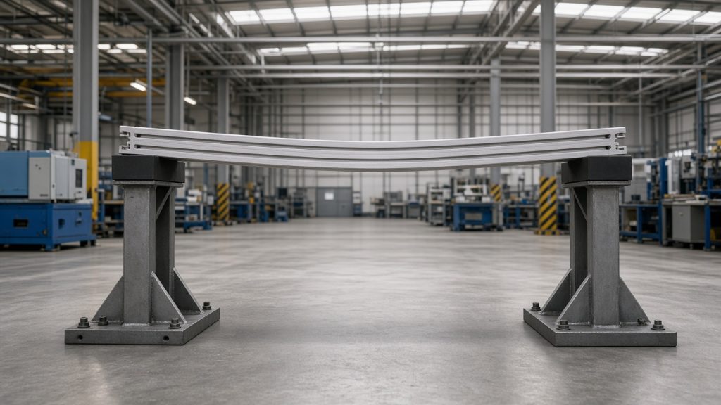
A 4040 profile carries about 150 kg over 2 m before deflection becomes the limit — not strength. Deflection governs, not yield: aluminium’s modulus is roughly one-third of steel’s, so serviceability (L/500 or L/360) fails long before the section reaches 6063-T5 yield.
Short answer
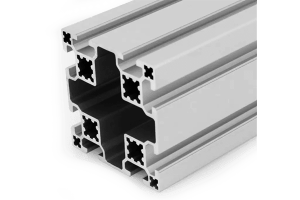
Size T-slot beams for allowable deflection, not for tensile yield. Use simply-supported mid-span load as a conservative screen: δ = F·L³ / (48·E·I) with E ≈ 69 GPa for 6063-T5. Catalogue-style tables often stop at L/1000; for automation and work surfaces prefer L/500 (2 mm at 1 m) and for general framing L/360. A typical 4040 (I ≈ 9–11 cm⁴) is stiff enough for many 1 m industrial bays; at 2 m the same section needs a second rail, a rectangular 4080 on the strong axis, or a mid support if you want flatness under heavy load. Site example: a 45 × 90 mm six-slot in 6063-T5 at 4.10 kg/m with I ≈ 68 cm⁴ on the strong axis. Extrusion tolerances EN 755-9: wall ±0.15 mm, straightness 1.5 mm/m, twist 2°. Fabrication: cut length ±0.5 mm, hole position ±0.2 mm, end square within 0.3 mm.
Is 3030 strong enough for a workbench
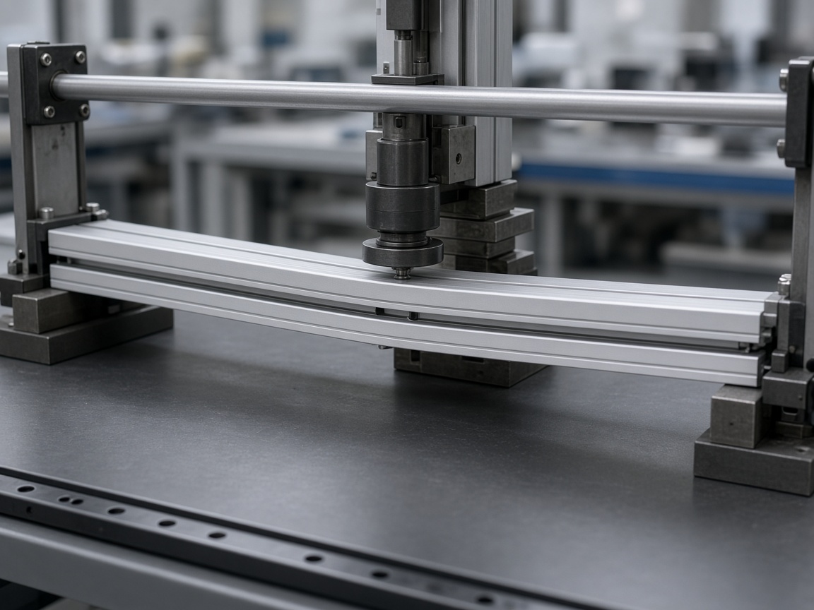
3030 is strong enough for a light workbench with short bays; it is usually not stiff enough as the sole perimeter of a loaded industrial bench, conveyor side rail, cleanroom equipment frame or CNC gantry at metre-class spans.
“Strong enough” in aluminium framing almost always means “stiff enough.” A typical 3030 has I around 2.5–3.3 cm⁴ and mass near 0.75–1.0 kg/m. Under a 50 kg mid-span load at 1 m, deflection is several millimetres — acceptable for a light assembly bench, not for a granite-feel top or a precision fixture base. Cleanroom equipment frames and CNC router gantries add vibration; conveyor frames add continuous distributed load. In those cases step to 4040 or a rectangular section, or shorten the bay with a post.
| Use case | 3030 verdict | When to upsize |
|---|---|---|
| Light workbench | OK if bays ≲ 0.8–1.0 m | Heavy tops or >1.2 m spans |
| Conveyor frame | Light belt, short pitch only | Default to 4040 / 4080 |
| Cleanroom equipment frame | Rarely as primary rail | 4040 for stiffness + anodise |
| CNC router gantry | No as sole beam | 4080+ or twin rails |
| Guard / light rack | Yes | Only if impact loads rise |
| Mobile cart deck | Borderline | 4040 if casters + load |
What profile for a workbench that must not deflect more than 1 mm
To hold mid-span deflection to about 1 mm on a workbench rail, you need either a short span, a high-I section (4080/4590 strong-axis or heavier), or multiple parallel rails — a lone 2020 or 3030 at 1 m will not meet a 1 mm limit under useful loads.
Rearrange δ = F·L³ / (48·E·I) for I_min = F·L³ / (48·E·δ). With E = 69 GPa, δ = 1 mm, L = 1000 mm and F = 500 N (~50 kg), I_min ≈ 15 cm⁴ — above typical 4040 and into 4545/4080 territory depending on the catalogue section. At 1.5 m the required I grows by (1.5)³ ≈ 3.4×. State the load case on the drawing (mid-point vs uniform) so the supplier quotes the matching I.
| Span | Load (mid) | ~I needed for 1 mm | Practical section |
|---|---|---|---|
| 0.8 m | 50 kg | ~8 cm⁴ | 4040 |
| 1.0 m | 50 kg | ~15 cm⁴ | 4545 / light 4080 |
| 1.0 m | 100 kg | ~30 cm⁴ | 4080 / 4590 strong |
| 1.5 m | 50 kg | ~51 cm⁴ | 4590 strong / twin 4040 |
| 1.5 m | 100 kg | ~100 cm⁴ | 8080 or multi-rail |
| 2.0 m | 50 kg | ~120 cm⁴ | 8080 / mid post |
Is 2020 stiffer than steel tube of the same outside size
No — a 2020 aluminium T-slot is not stiffer than a steel tube of the same outside envelope; aluminium’s E ≈ 69 GPa versus steel’s ~210 GPa means equal geometry deflects about three times more in aluminium.
T-slot wins on mass, corrosion resistance, modular hardware and cut-to-length fabrication — not on modulus. A thin-wall steel tube can still beat 2020 on bending stiffness while weighing more. Designers who need aluminium for hardware modularity compensate by upsizing the section (4040 or 4080) until I recovers the factor of three. Comparing only outside size without I and E is a false test.
| Member | E (GPa) | Relative δ (same I) | When to choose |
|---|---|---|---|
| 2020 Al T-slot | ~69 | ~3× steel | Light modular frames |
| 3030 Al T-slot | ~69 | ~3× | Mid modular |
| 4040 Al T-slot | ~69 | ~3× | Industrial modular |
| Steel tube same OD | ~210 | 1× | When modulus dominates |
| Al rectangular upsized | ~69 | Recover via higher I | Keep Al hardware |
How strong is a 2020 aluminium profile
A 2020 profile is “strong” enough in yield for light fixtures, but its usable capacity in frames is set by deflection and joint hardware, not by 6063-T5 tensile numbers.
Typical 2020: mass ~0.5 kg/m, I ~0.7 cm⁴, slot ~6 mm. At 500 mm mid-span, catalogue L/1000 allowable loads are on the order of 10 kgf; at 1000 mm they fall to a few kgf. 3030 (~3 cm⁴) multiplies stiffness several times; 4040 (~9–11 cm⁴) roughly an order of magnitude over 2020; 4080 on the strong axis jumps again. Quote strength as allowable load at a stated span and deflection ratio, or as I on the print — never as a single kilogram number without length.
| Section | ~Mass (kg/m) | ~I (cm⁴) | Role |
|---|---|---|---|
| 2020 | 0.5 | ~0.7 | Light / short |
| 3030 | 0.9 | ~2.8–3.3 | Light–medium |
| 4040 | 1.5 | ~9–11 | Industrial default |
| 4080 (strong) | ~3.0 | ~60–75 | Long / heavy bay |
| 4545 | ~1.8 | ~14–15 | 45-series frames |
| 4590 (strong) | 4.10* | ~68* | Wide industrial rail |
*Site example: 45 × 90 mm six-slot, 6063-T5, 4.10 kg/m, I ≈ 68 cm⁴. Exact I varies by cavity design — use the mill drawing.
How do I calculate deflection of a 3030 beam
Calculate 3030 (or any T-slot) deflection with the Euler beam formula for your support case, using the catalogue I and E ≈ 69 GPa — then compare δ to L/500 or L/360, not to yield stress.
Simply supported, concentrated mid-span load: δ = F·L³ / (48·E·I). Simply supported, uniform total load W: δ = 5·W·L³ / (384·E·I). Cantilever end load: δ = F·L³ / (3·E·I). Keep units consistent (N, mm, MPa=N/mm², mm⁴). Example: I = 3.0 cm⁴ = 3.0×10⁴ mm⁴, L = 1000 mm, F = 200 N, E = 69000 N/mm² → δ ≈ 2.0 mm, which is L/500. Joints and open slots reduce real stiffness versus a perfect prismatic beam; treat the calculation as a screen and validate critical members.
| Support / load | Formula | Use when |
|---|---|---|
| Simple / mid point | FL³/(48EI) | Conservative screen |
| Simple / uniform | 5WL³/(384EI) | Distributed top load |
| Cantilever / end | FL³/(3EI) | Overhangs, arms |
| Fixed-fixed / mid | FL³/(192EI) | Only if ends truly fixed |
| Limit check | δ ≤ L/500 or L/360 | Acceptance on drawing |
What is the maximum unsupported span by size
Maximum unsupported span is the length at which your chosen deflection limit is reached under the design load — not a single catalogue number — so the table below gives section properties you can drop into the formulas above.
Indicative values for common industrial T-slot families (6063-T5). Wall and I vary by die; confirm on the section drawing. Tolerances referenced to EN 755-9: wall ±0.15 mm, straightness 1.5 mm/m, twist 2°.
| Section | Weight (kg/m) | Ix (cm⁴) | Wall (mm) | Tolerance |
|---|---|---|---|---|
| 3030 | ~0.90 | ~2.8–3.3 | ~2.0 | EN 755-9 |
| 4040 | ~1.50 | ~9–11 | ~2.0–2.5 | EN 755-9 |
| 4080 | ~3.00 | ~18 (weak) / ~65 (strong) | ~2.5 | EN 755-9 |
| 4545 | ~1.80 | ~14–15 | ~2.0–2.5 | EN 755-9 |
| 4590 | 4.10* | ~68* strong | ~2.5 | EN 755-9 |
| 5050 | ~2.50 | ~22–27 | ~2.5 | EN 755-9 |
| 8080 | ~5.00 | ~125–140 | ~3.0 | EN 755-9 |
| 9090 | ~7.00 | ~200–210 | ~3.0 | EN 755-9 |
| 100100 | ~9.00 | ~260–270 | ~3.0–4.0 | EN 755-9 |
*45 × 90 mm six-slot example used on this site: 6063-T5, 4.10 kg/m, I ≈ 68 cm⁴.
Worked span screen (L/500, mid-point load, E = 69 GPa). Approximate allowable F at 1 m: 3030 ~100–120 N; 4040 ~350–450 N; 4080 strong ~2.5–3 kN; 8080 ~5 kN class. At 2 m, allowable F falls by about 8× for the same δ/L. That is why a 4040 “150 kg at 2 m” claim only holds with generous deflection, multiple rails, or a different support model — always write the limit on the RFQ.
RFQ checklist — span and load
- Section and orientation — e.g. 4080 with 80 mm depth vertical.
- Span and support — simple, continuous, or cantilever.
- Load case — mid-point kg or uniform kg/m.
- Deflection limit — L/500, L/360 or absolute mm.
- I from drawing — do not assume a generic catalogue I.
- Alloy / temper — usually 6063-T5 for T-slot.
- Metres / die — 150 m existing, 500 m new.
Put δ ≤ L/500 (or your mm number) on the enquiry. That single line prevents strength-vs-stiffness arguments later.
Four span mistakes
Related on this site
- how die cost amortises per meter— cost after you lock the section
- minimum order with a new die— 150 m vs 500 m
- die making adds 7–12 days— schedule before first bars
- who owns the die— tooling title
Terms used in this article
- Second moment of area (I)
- Section property that sets bending stiffness; units cm⁴ or mm⁴.
- L/500
- Deflection limit equal to span/500 (2 mm at 1 m); common for automation flats.
- L/360
- More permissive framing limit (about 2.8 mm at 1 m).
- E (modulus)
- ~69 GPa for 6063 aluminium; ~210 GPa for steel.
- EN 755-9
- Dimensional tolerances for extruded aluminium used on this page.
Questions buyers ask
What standard are the tolerances measured against?
Extruded dimensions on our industrial profiles are referenced to EN 755-9: wall ±0.15 mm, straightness 1.5 mm/m, twist 2°. Fabricated features after sawing and CNC follow cut length ±0.5 mm, hole position ±0.2 mm and end square within 0.3 mm unless the drawing tightens them.
Can you supply a mill certificate?
Yes — a mill test certificate for alloy and temper (typically 6063-T5 for catalogue T-slot) can ship with the lot. Ask for EN 10204 type on the PO if your QA system requires it. Mechanical values on the cert confirm chemistry and temper; they do not replace a deflection check using I.
What is the minimum wall thickness?
For catalogue T-slot dies the wall is set by the tool — commonly around 1.5–3 mm depending on series. Custom dies can go thinner in 6063 than in 6061/6082, but tongue length in deep slots and press limits still apply. State a minimum wall on the drawing if anodising or structural calculation needs it.
How is weight per metre calculated?
Mass per metre is section area × density (~2.70 g/cm³ for 6063) from the die drawing, then verified on weighed bars. Catalogue kg/m is nominal; anodising adds a small mass. Use the drawing value for shipping weight estimates and the measured I for deflection.
Send the span, load and deflection limit
Give unsupported length, kg (point or uniform), L/500 or mm limit, and preferred section. We will return I-based allowable load and confirm EN 755-9 tolerances on the drawing before you order metres.
Request a quoteRelated reading
Twelve more engineering notes from this blog, picked for this article — plus every category below.
 ApplicationsBuilding with T-Slot: Frames, Fences, Workbenches and Guards
 Engineering DesignSlot Dimensions Explained: 6 mm, 8 mm and 10 mm T-Slots
 ApplicationsWhere Modular Aluminium Framing Works: A Load-Tier Map Instead of an Industry List
 Engineering DesignHeavy-Duty T-Slot Hinges and Sliding Door Buffers: Sizing Them with Numbers
 Engineering DesignAluminum vs Steel Machine Frames: Choose by Deflection, Not by Strength
 Engineering DesignAluminium Profile Sizes 20 × 20 to 100 × 100: What Fails First
 Applications20 Series T-Slot Profiles: Where the Limits Actually Are
 Applications40×40 Aluminium Profile: Where It Works, Where It Fails, and Why
 Quality and InspectionGlobal Sourcing Excellence: Multi-Category OEM and ODM Manufacturing and Supply Chain Integration
 Quality and InspectionSampling and First Article Approval for Aluminium Extrusion
 ApplicationsAluminium Profiles in Solar Mounting: Wind Uplift, Corrosion and a 25-Year Life
 Sourcing and ProcurementAluminium Profile Shipping: Packing, Container Loading and ISPM 15
