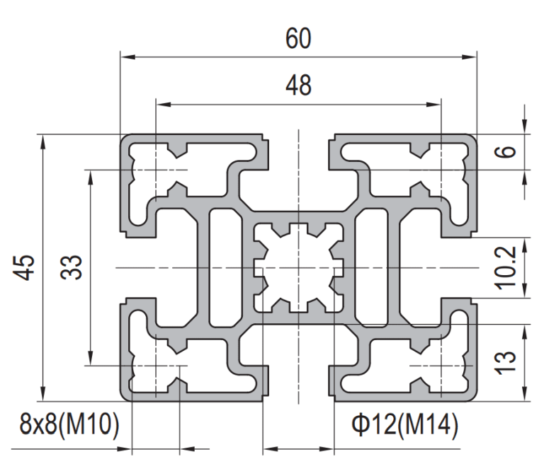
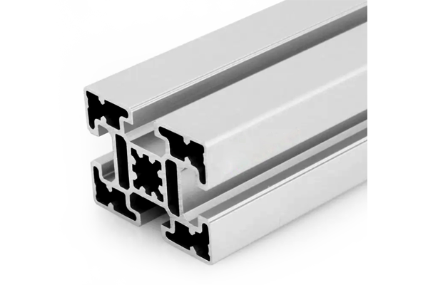
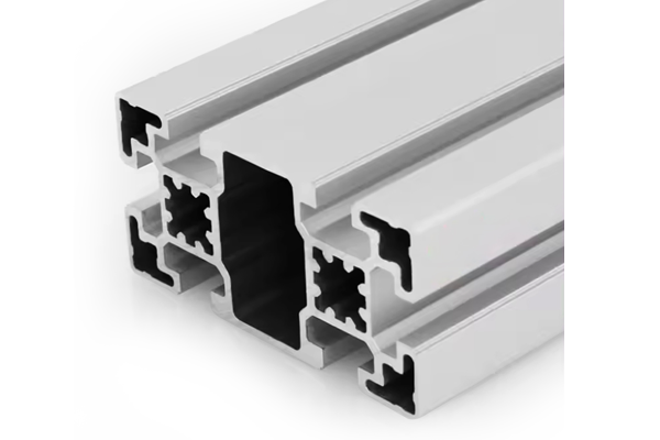
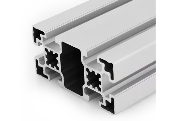
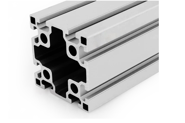
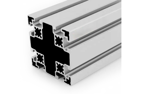
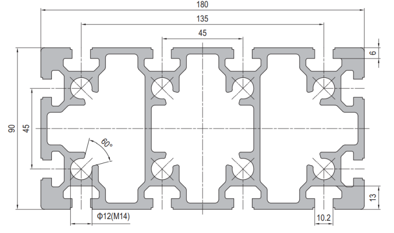
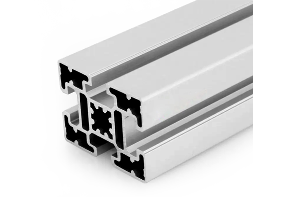
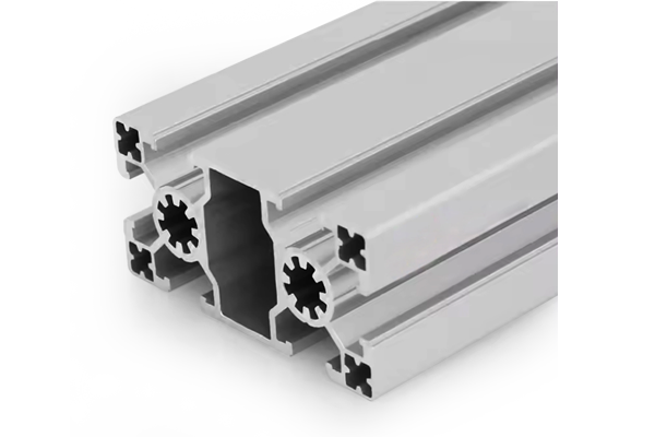
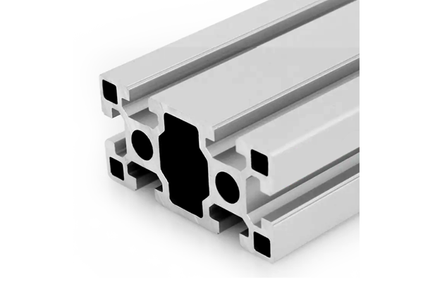
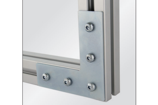
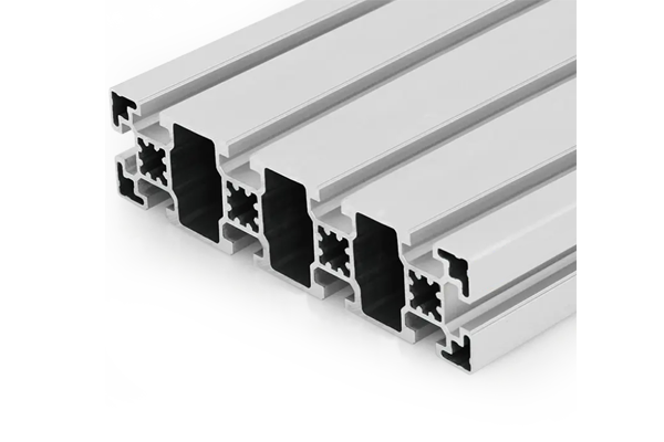
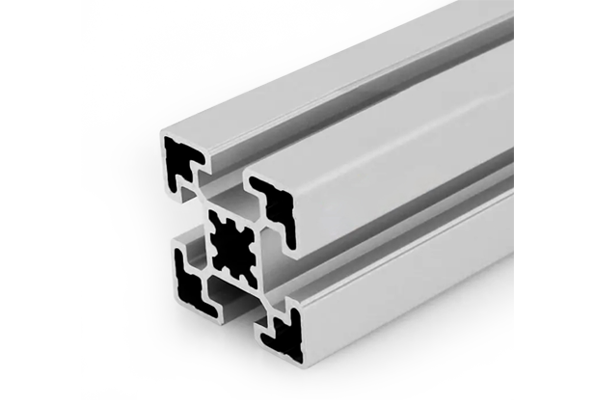
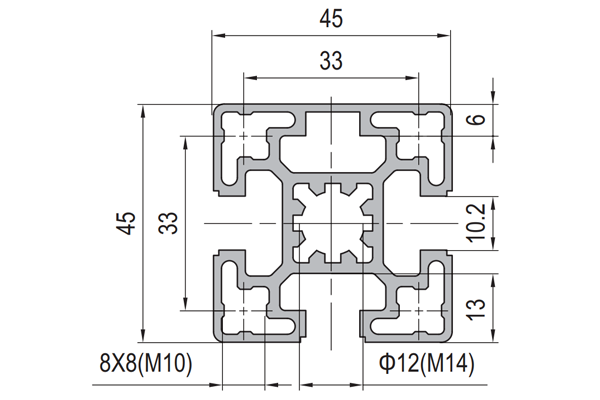
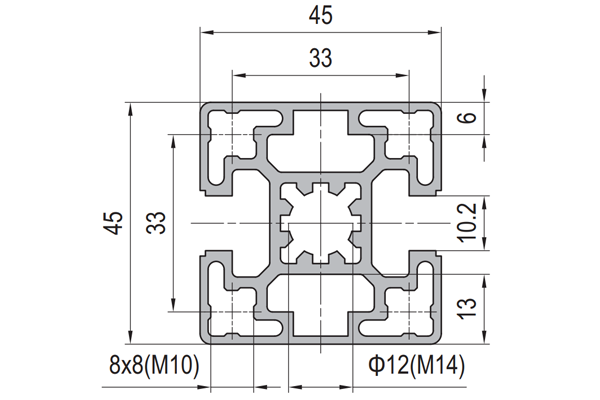
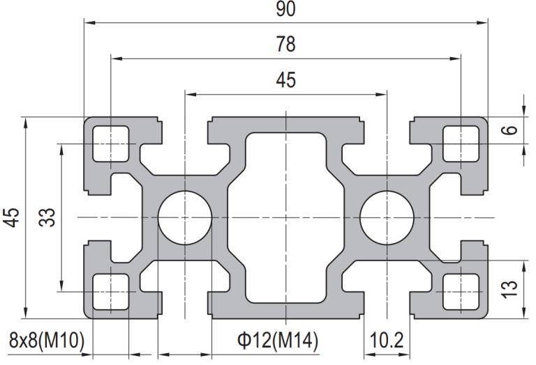
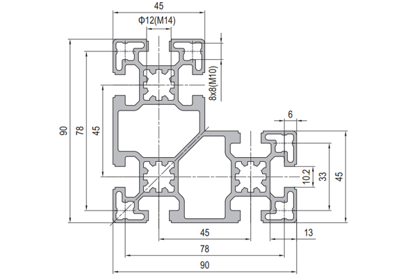
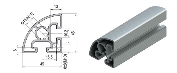
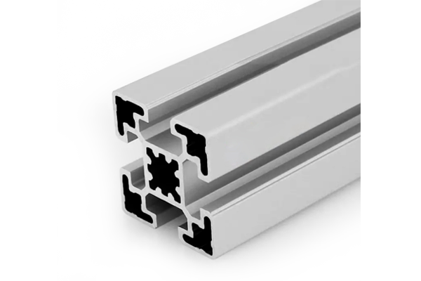
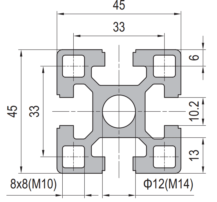
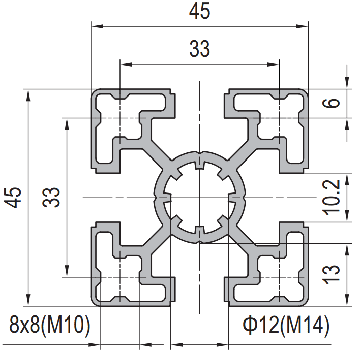
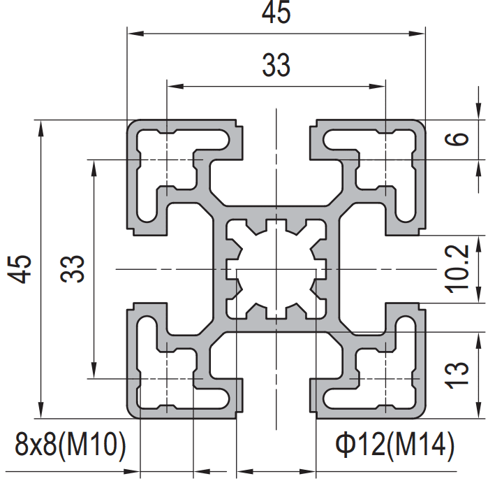
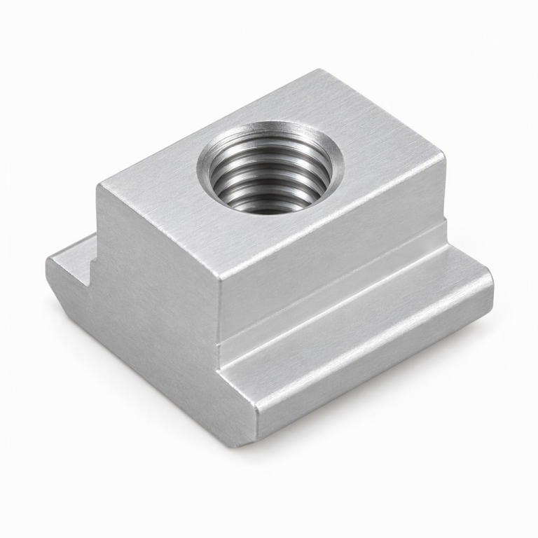
45 series aluminium profiles are slotted extrusions on a 45 mm module with a 10 mm T-slot. The common sizes are 45×45, 45×60, 45×90, 45×120 and 90×90. They take M8 T-nuts, exactly like 40 series, which is why the two systems are so often confused — but the module and the slot-to-slot distance differ, so a 45 series bracket will not bolt correctly onto a 40 series profile. Some catalogues list the range as PG45.
Below: how to identify which module you have, why the difference matters at the joint rather than in the section, and how to decide between 40 and 45 series.
Why 40 and 45 series are not the same system
Both series use a 10 mm slot and both accept M8 T-nuts. If you only look at the fastener, they appear identical, and that is where the confusion starts. The difference is in the geometry around the slot.
The module sets where the slots sit on the section and therefore where the bolt holes in a bracket fall. A 40 series profile has its slots on a 40 mm pitch; a 45 series profile has them on a 45 mm pitch. A die-cast corner bracket is drilled to one pitch or the other. Fitting a 45 series bracket to a 40 series profile means one hole lands correctly and the other does not — which produces a joint that appears to tighten but never pulls square, and which will move under load.
Practical point: the reliable way to identify a profile is not to measure the slot. Measure the outside of the square section and check the distance from the outside face to the slot centreline. A 40 mm square with a 10 mm slot and a 45 mm square with a 10 mm slot are visually similar at arm's length and geometrically incompatible at the bracket.
How to tell which module you are looking at
| Check | 40 series | 45 series |
|---|
| Outside square | 40 mm | 45 mm |
| Slot width | 10 mm | 10 mm |
| Slot pitch | 40 mm between opposite slot centrelines | 45 mm between opposite slot centrelines |
| Fastener | M8 standard, M10 on heavy sections | M8 |
| Bracket interchange | Not interchangeable with 45 series | Not interchangeable with 40 series |
| Mixing | Needs an adaptor plate | Needs an adaptor plate |
Measuring a single dimension is enough to separate them: if the square is 45 mm rather than 40 mm, everything downstream changes.
The common sizes and what they are used for
| Section | Slots | Typical role |
|---|
| 45×45 | 4 | General frame members, posts, brackets |
| 45×60 | 6 | Frame uprights and horizontals where the 45 mm module is already in use |
| 45×90 | 8 | Beams and frame sides; the usual upgrade from 45×45 when a span grows |
| 45×120 | 10 | Longer spans, wide openings, gantry rails at moderate load |
| 90×90 | 8 | Machine bases and heavy uprights within the 45 system |
In practice the family behaves like the 40 series family: 45×45 is the base member, 45×90 does most of the work in a machine frame, and 90×90 appears at bases and columns. The design guidance on span, orientation and bracing is the same, and is set out in more detail on the 40 series page.
When a project forces the 45 module
Nobody chooses 45 series for its geometry. It gets chosen for one of four reasons.
- An existing frame has to be extended. Matching what is already installed is almost always cheaper than replacing it, even if 40 series would have been the better original choice.
- A customer specification names it. European machine builders and some automotive standards work in the 45 module, and a tier-one supplier has no discretion.
- The accessory catalogue is deeper. Some regions have a far wider range of hinges, handles and panel fittings in 45 series than in 40, and the accessory range can decide the frame.
- A tender is written around it. Where a drawing package already specifies 45 series profiles and brackets, switching means re-approval.
If none of those apply, 40 series is usually the better default: it is more widely stocked, the accessory range is broader in most markets, and a 40×80 section gives more depth in the bending plane than a 45×45 at comparable weight.
Mixing 40 and 45 series in one structure
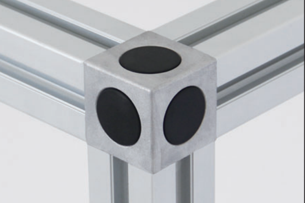
Mixing is possible but should be limited to one or two joints. The standard solution is a flat adaptor plate drilled for both pitches, bolted to each member with its own series hardware. The plate has to be thick enough not to dish when the bolts are tightened, and it should be positioned so the load passes through the plate rather than relying on friction between the two members.
Two cautions. First, an adaptor plate adds a joint, and a joint is the weakest part of any frame — keep adaptors away from highly loaded corners. Second, an adaptor is a single point of failure for the whole order: if it is missing, nothing assembles. Where a structure genuinely needs both modules, order the adaptor plates with the profiles and check them on receipt.
Hardware, cutting and finishing
45 series hardware is an M8 family: T-nuts, hammer nuts, flange nuts and the associated bolts. Because the slot is 10 mm, the same bolt lengths that suit 40 series generally work, but the T-nut profile is different and must be ordered for the correct series. The full family is described under fastening elements, with the structural connectors under connecting elements.
Cutting and machining practice matches 40 series: cut to ±0.3 mm with square ends, deburr, and plan any end taps before cutting because a concealed connector needs a tapped or counterbored end. Satin anodised is the standard finish in clear, black or bronze; see anodised aluminium profiles for film grades and their dimensional effect.
Specifying a 45 series order
State the series explicitly as "45 series, 10 mm slot" and give the section, the finish, the cut list and the quantity. If you are matching an existing installation, send a short offcut or the section dimensions — identifying the module from a photograph is unreliable. Standard sections are quoted within one working day. Related ranges: 40 series, 50 series, strut profiles, connecting elements and CNC machining.